![[protofusion]](http://protofusion.org/wordpress/wp-content/uploads/2013/02/protofusion-text2.png)
The ability to make good espresso is one of the most coveted skills in the coffee world. The rich body and complex flavor profile of a well-made shot brings the beans to life with a depth that other brewing methods fail to achieve. But espresso is also among the more complicated ways to make coffee. Fine grinds, high pressures, short brew times, metered doses, and precise temperatures all work together to create the perfect shot – but a variation in any one of these variables can just as easily render it undrinkable. Making consistently good espresso requires consistent brewing parameters.
Unfortunately, traditional consumer-grade espresso machines are not very good at keeping water temperature consistent. They typically manage the boiler temperature with thermal cutoff switches, which have a large temperature range, switching off the heater when the temperature reaches the top of the range, and switching back on when it gets to the bottom of the range. This can result in temperature swing of 10°C or more, but espresso requires a precision of at least 1°C for reliable results. Because of this, many home baristas will learn to “temperature surf” by measuring the boiler temperature at various points in the heating cycle and tracking the time after the thermal cutoff switch turns off to hit their desired brew temperature. This technique is very tedious to execute correctly and is subject to variations in individual machines and environmental conditions.
The best way to keep the boiler temperature consistent is by implementing a PID control algorithm, which is designed to optimally regulate temperature and can easily achieve sub-degree accuracy. There are many commercial PID controllers available on the market, but they each have drawbacks such as size, cost, and customizability. To overcome these hurdles and create a solution that meets our temperature control needs, Protofusion has developed a tiny open-source PID controller called Therm.
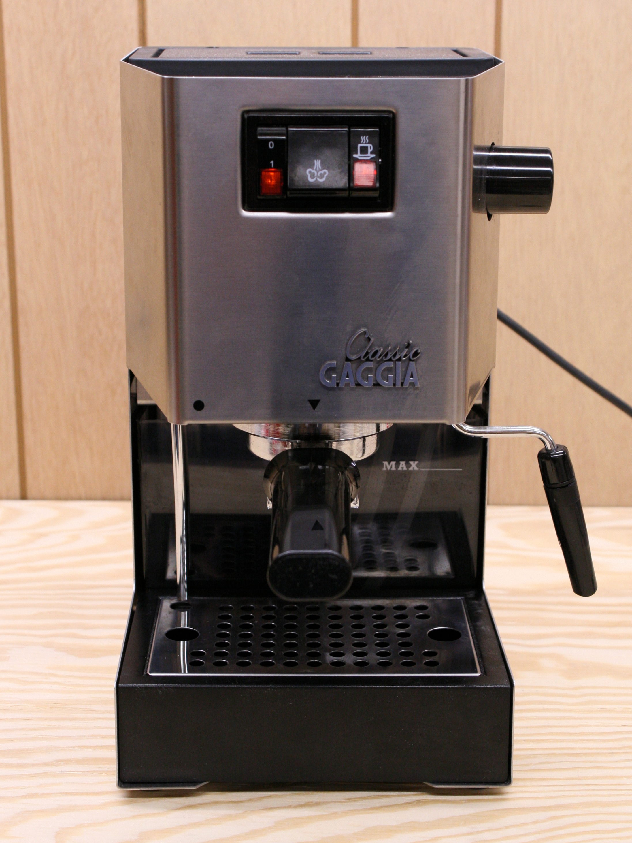
Therm uses a thermocouple to measure temperature and has a digital output that can be paired with a solid state relay (SSR) to control heating elements or other thermal devices. Because the software is open source, it is easy to add new parameters, control strategies, and features. For this project, we will use Therm to control the boiler temperature of the Gaggia Classic espresso machine and configure the software to read in the state of the switches on the front of the machine to select between brew and steam temperatures. This seamless integration will preserve the existing machine interface and aesthetic while providing the benefits of precise and stable PID-controlled boiler temperatures.
Start to finish, it took me about 2 hours to complete this project. I would imagine the whole thing could be achieved in an afternoon by anyone comfortable around tools and with basic soldering experience.
Schematics
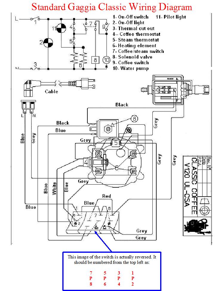
Above is the schematic and wiring diagram for an unmodified Gaggia Classic machine. This is the starting point for the modifications we’ll make, and we’ll try to leave as much of the system as possible undisturbed. In fact, if you follow the directions here, it should be very easy to revert the machine back to the stock configuration.
The first addition to the system is a Therm module to act as the new brains of the machine. Therm runs on a 5V power supply, which doesn’t exist in the stock machine, so we’ll need to add that too. To measure the temperature of the boiler, we’ll need to add a thermocouple. We also want to remove the old thermal cutoff switch that was used to control the brew temperature. Physically removing the cutoff switch is not strictly required, but it leaves a nice place to install the thermocouple, so I would recommend it. Either way, we’ll want to take it out of the circuit and replace it with a solid state relay. The SSR will turn on and off to regulate the temperature just like the cutoff switch did, but it will be controlled by Therm rather than a mechanical thermal mechanism.
Next, we need a way to tell Therm whether the machine is in brew mode or steam mode, so it can set the temperature setpoint accordingly. In the stock machine, the steam selector switch on the front panel is used to bypass the brew cutoff switch, which will allow the temperature to go up to the limit imposed by the steam cutoff switch. But now, we want Therm to control the temperatures and not the cutoff switches. To do that, we’ll disconnect the steam selector switch from the cutoff switch, and instead, connect it to an input on Therm.
I decided to leave in the steam cutoff switch because it will help protect the boiler from getting too hot. The machine also has a thermal fuse that will trigger if everything else fails, but since it is a single-use fuse, I didn’t want to risk blowing it while I was tuning my Therm settings. I did, however, decide to upgrade my steam cutoff switch with a 155°C replacement, which should help the machine deliver a larger volume of steam from the boiler compared to the stock 145°C cutoff. This upgrade is completely optional as it doesn’t directly influence the PID control system, but it may be worth considering since you already have the machine open.
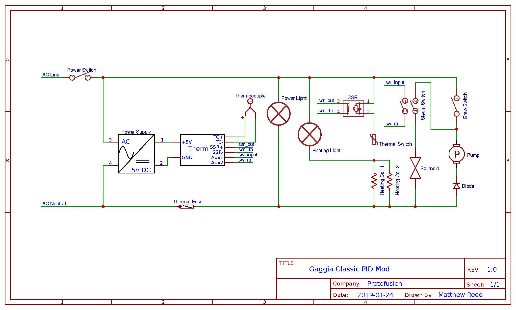
Below is an updated schematic which shows all of the changes we want to make to the system. Next, we’ll look at the specific parts we’ll need and then go through each step required to complete the modification.
Parts List
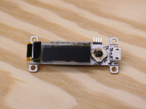
Therm: Therm is a open source PID temperature controller created by Protofusion. Unfortunately, it is not currently available for sale, but since it’s completely open source, you’re welcome to download the design files and fabricate one yourself!
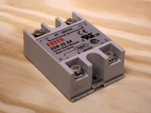
Solid State Relay: SSRs can be cheaply sourced from places like eBay, but be careful not to skimp on this part. The Gaggia Classic has a max power consumption of more than 1400W, which can easily burn up a cheap SSR. If the brand or source is questionable, I would recommend derating the current by a factor of 2 or 3 and going for a model rated for 25-40A just to be safe.
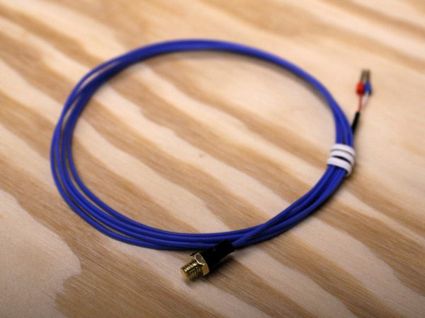
Thermocouple: Thermocouples are used to precisely measure temperature. They come in all shapes and sizes for many different applications and can have a wide range of price points. Fortunately, several popular low-cost 3D printers use a thermocouple with an M4 thread that perfectly matches the thread of the thermal cutoff switch we are removing, making it easy to find and a perfect drop in replacement for this modification.
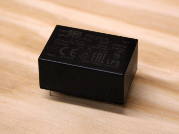
Power Supply: The Therm PID temperature controller needs a 5V power supply, but the only power available in the stock machine is 120V AC. Just about any AC to 5V power supply will work, since Therm doesn’t consume much power, but I chose this MeanWell module for its low cost, small form factor, and easy connection points. A basic USB phone charger would also work well if you have an old one laying around.
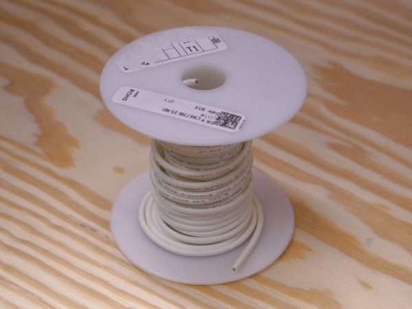
High Temp Wire: Wire rated for high temperatures is a good idea for this modification because the inside of an espresso machine can get hot enough to melt standard wire insulation. I chose wire with silicone insulation and a 200°C rating. You’ll need some relatively heavy gauge wire for wiring the heaters, but the signal wires for the SSR control and steam selection switch can be much smaller. I used 16 gauge wire for the high power lines and 22 gauge wire in red, blue, and black for the low power circuits.
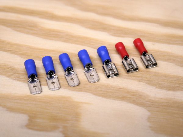
Spade Connectors: Spade-style quick connect terminals are used in the stock espresso machine wiring, and it’s nice to be able to plug the new circuit additions directly into the existing harness connectors. This isn’t strictly required, and there are plenty of other ways to create electrical connections, including splices, solder joints, and different connector styles.
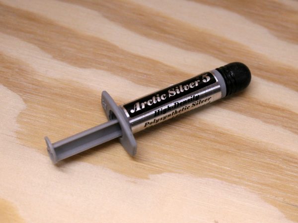
Thermal Paste: Thermal paste is used to improve heat transfer. In this case, we want temperature changes in the boiler to influence the thermocouple as quickly as possible. While not absolutely necessary, a dab of thermal paste will help to improve the accuracy and response time of the temperature measurements. (Any old thermal paste will work well – Arctic Silver is definitely overkill, but it’s what I had on hand.)
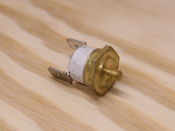
155°C Thermal Cutoff Switch (Optional): The stock machine comes with a 145°C thermal cutoff switch for steam temperature, which restricts the amount of steam that can be made in the small boiler. Upgrading to a 155°C cutoff should significantly improve the available steam volume.
Required Tools
- Screw drivers
- Adjustable wrench or wrench set
- Wire cutters
- Crimpers or pliers
- Soldering iron
Detailed Steps
Here are more detailed instructions on making the modifications step by step:
 1. Open up the machine
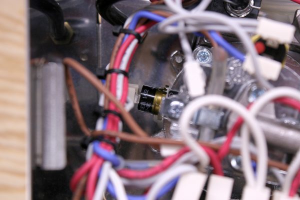 2. Remove brew cutoff switch
 Brew cutoff switch
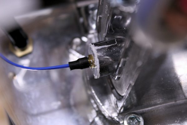 3. Install thermocouple
 4. Replace steam cutoff switch
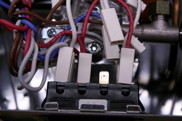 5. Disconnect steam switch on front panel
 6. Wire up SSR
 6. Connect SSR
 7. Wire up power supply
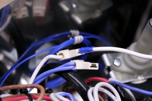 7. Connect power supply
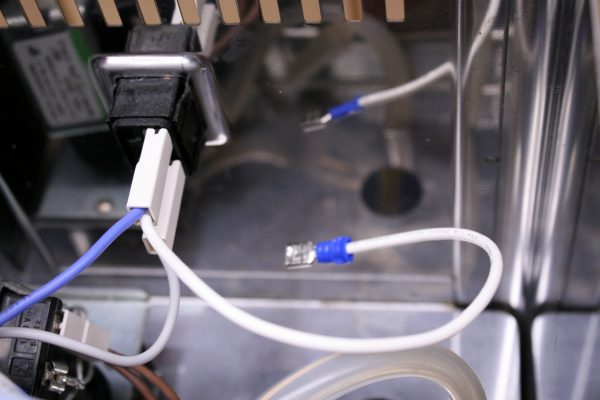 7. Connect power supply
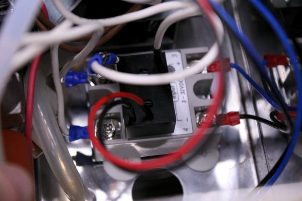 7. Connect power supply
 8. Wires for steam switch
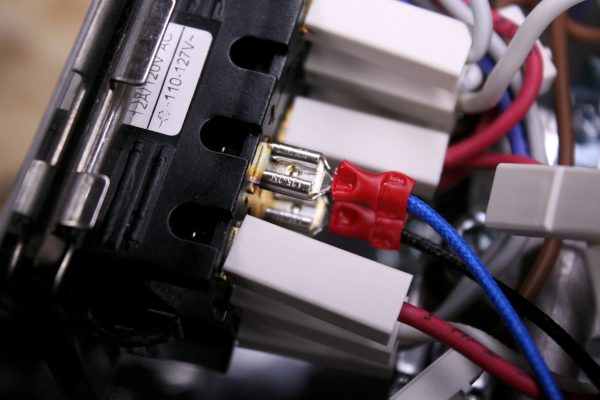 8. Connect steam switch
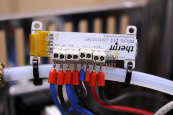 8. Install Therm
 8. Install Therm
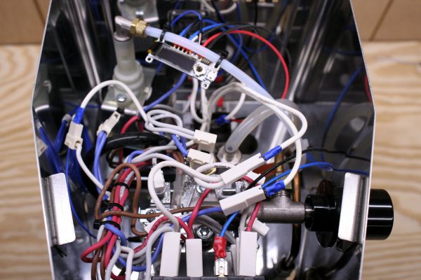 9. Reassemble the machine
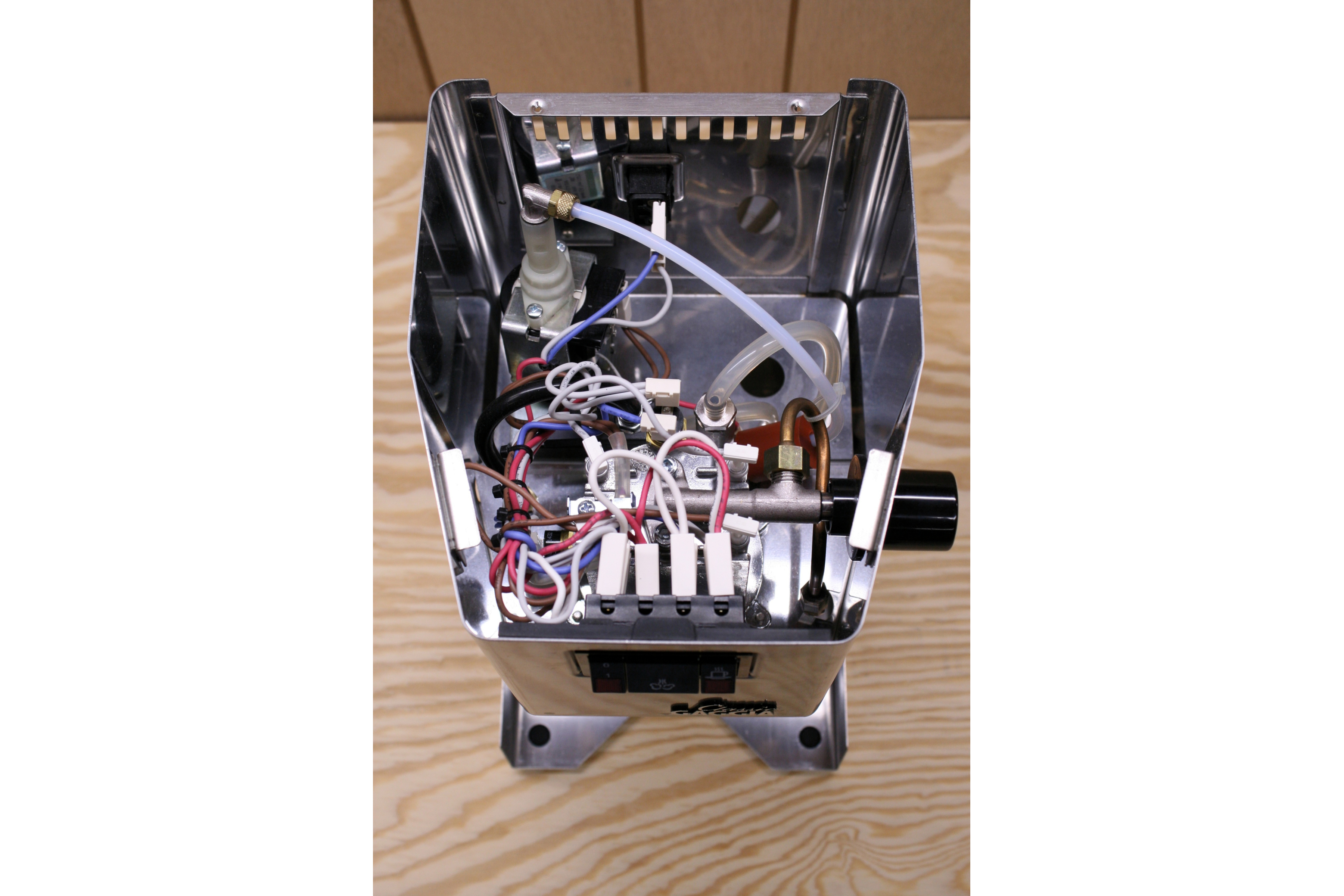


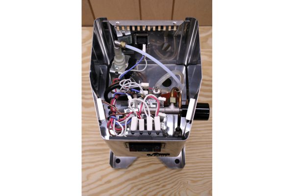
- Open up the machine: Remove the two screws along the back of the top cover and take off the cover, along with the water funnel.
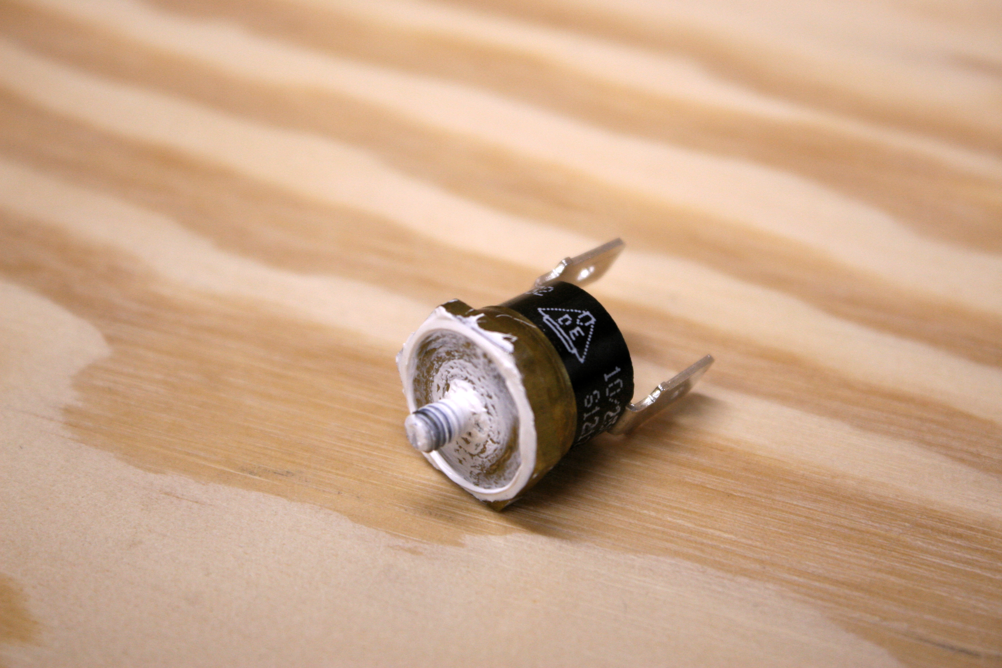
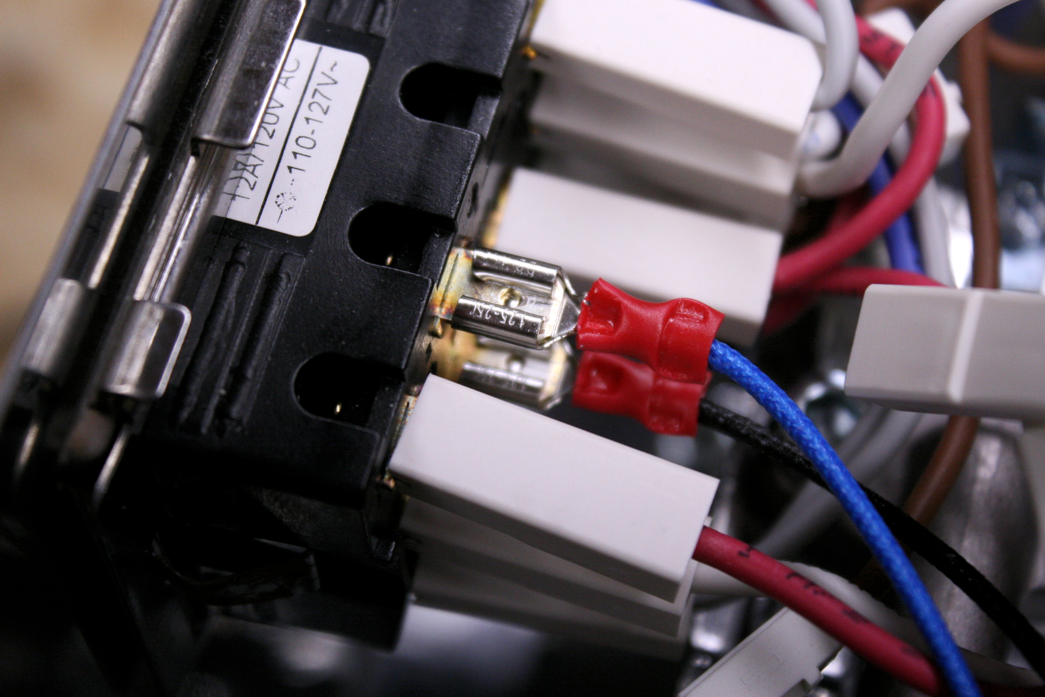
- Remove brew cutoff switch: The brew thermal cutoff switch is located on the side of the boiler, opposite the steam knob. It’s threaded into a mounting hole and you might see some some white/gray thermal paste coming out around the edges. Disconnect the spade connectors plugged into it, and use a wrench to back it out.
- Install thermocouple: The thermocouple in the parts list has an M4 thread to match the cutoff switch thread, so installing the thermocouple is as easy as screwing it into the open hole. A bit of thermal paste on the tip before installing is recommended, but not required, especially if there’s lots of thermal paste left from old switch.
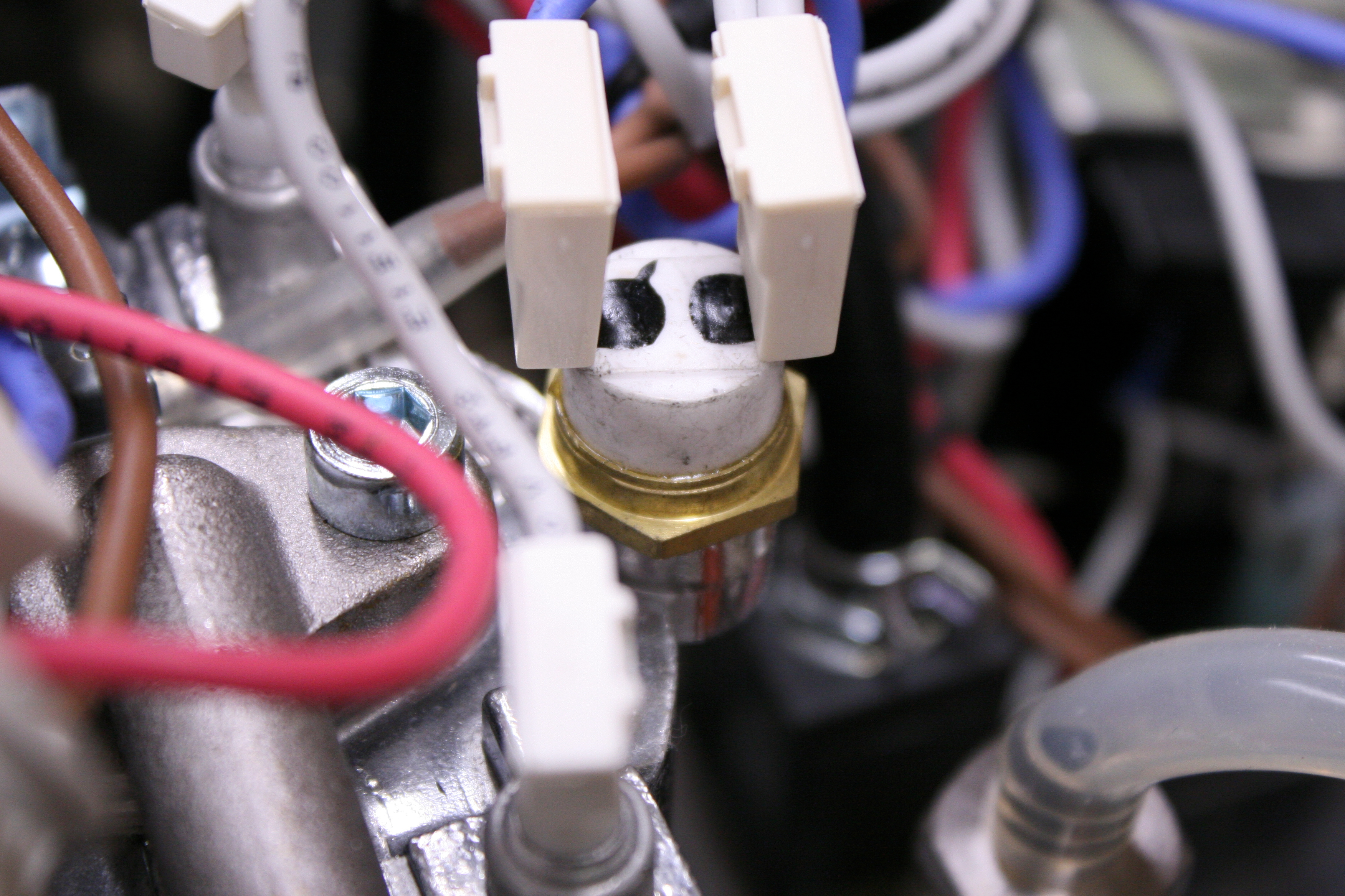
- Replace steam cutoff switch (optional): If you opted to upgrade the steam thermal cutoff switch, you can swap that out now. The steam cutoff is found on the top of the boiler, and looks just like the brew switch. Make sure you reconnect the wires once the new device is installed.
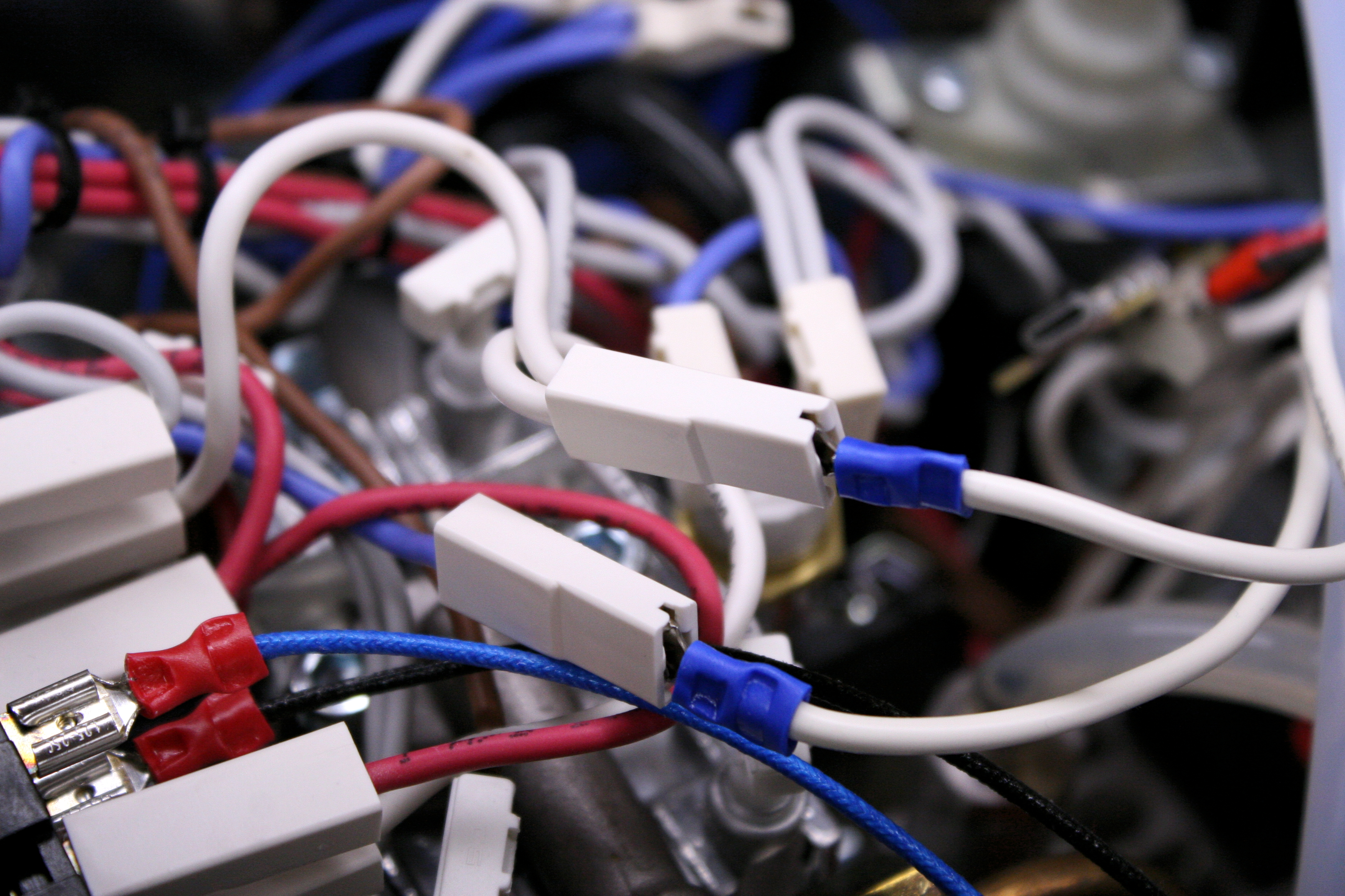
- Disconnect steam switch on front panel: The steam switch is double pole, which means it has two separate circuits running through it. We only want to disconnect the side that goes to the heater coil, which is the side closer to the brew switch. Disconnect both the top and bottom connectors. In my machine, the top connector had two gray wires and the bottom one had a single blue wire.
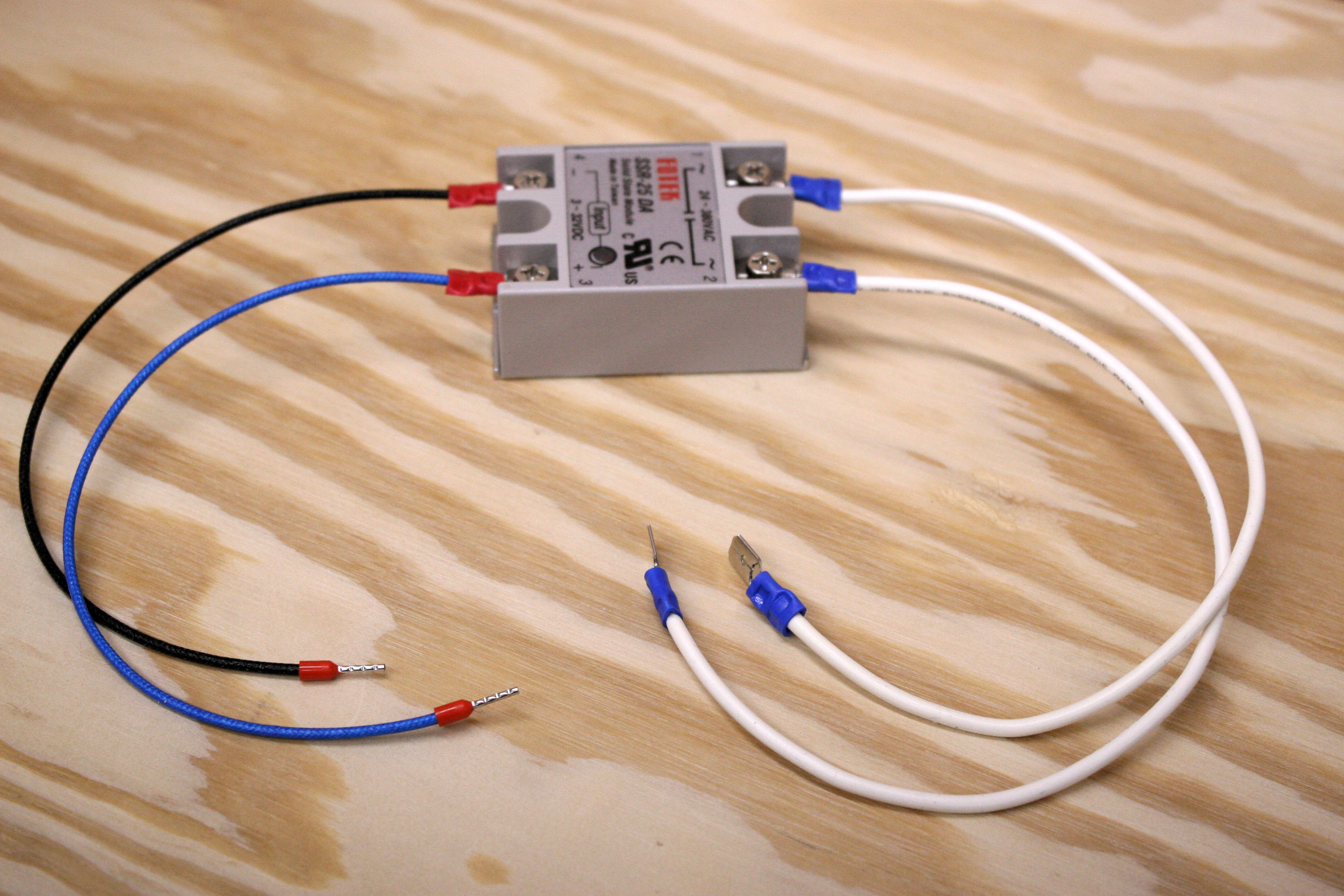
- Wire up and connect SSR: Use the heavy gauge wire to add leads to the SSR output side and terminate them with male spade connectors. Since the SSR takes the place of the front panel steam switch in this circuit, we’ll want to connect the output directly to the wires we just unplugged from the front switch. Plug the male spades into the female connectors from the front panel switch. Add wires (thinner wire is fine) to the SSR +/- input to connect to Therm.
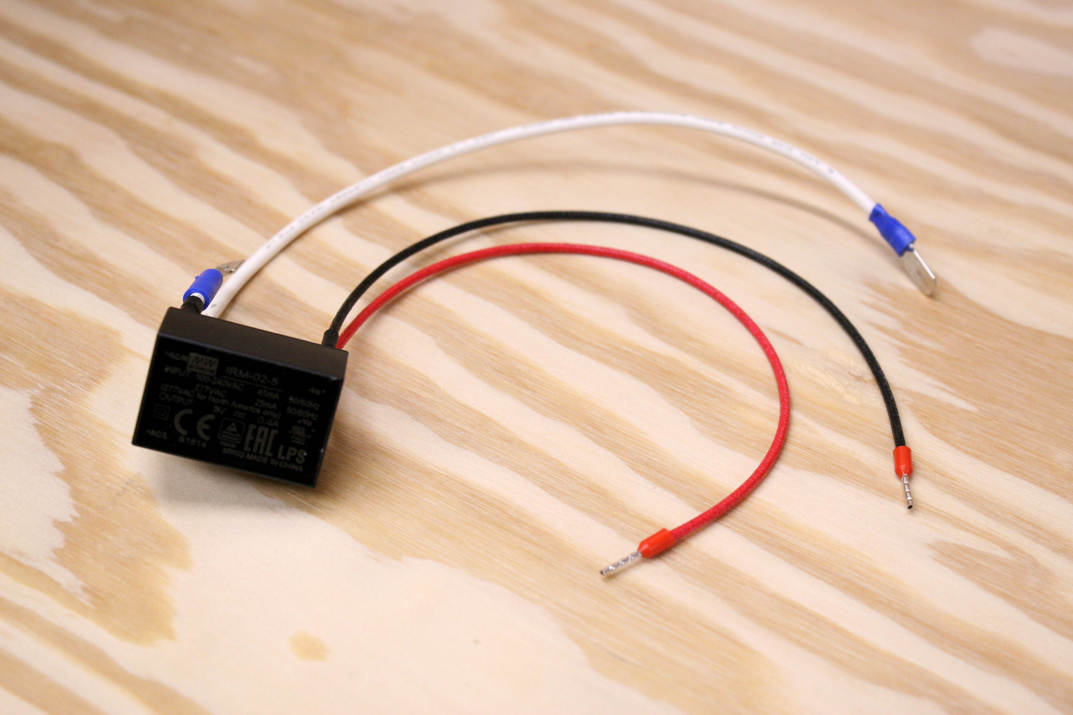
- Wire up power supply: The 5V power supply needs to connect to the AC power coming into the machine, preferably after the power switch. For the AC hot connection, I used the connectors that were unplugged from the brew thermal cutoff switch (on mine, the hot side had a single gray wire). For the neutral connection, I spliced a wire with a connector into the neutral line going out to the power plug. Wire up the power supply and connect the AC hot/neutral to the machine, leaving 5V wires ready to connect to Therm.
- Wire up and install Therm: Use female spade connectors and the thinner wire to connect the front panel steam selection switch to the Therm aux pins. Also connect the thermocouple, SSR input, and 5V lines to the matching Therm ports. I used ferrules to terminate the wires going to the Therm screw terminals, but bare wires would also work just fine.
- Reassemble the machine: Double check that all of the wires are hooked up, and then replace the top cover and the water funnel, along with the screws that were removed during disassembly.
Conclusion
You’ll be amazed at how consistent the Gaggia Classic can be in creating repeatable shots when the boiler temperature is stable. PID temperature control allows you to focus on the art of pulling a good shot, instead of constantly worrying about fluctuating brew temperatures.
Matthew is a computer engineer who enjoys designing hardware for embedded control systems. His hobbies include photography, gardening, coffee, and anything DIY.
Ballpark ?
Conspicuously absent !
I apologize – the omission was not intentional! If you look at the cost of each item on the parts list, the total comes to somewhere around $60. It cost me a bit less because I had some of the parts (wire, connectors, thermal paste, etc) laying around already.
Hi there,
I’m currently working on an open source espresso machine project (https://hackaday.io/project/162176-open-source-espresso-machine) and this would be perfect to implement! If you would like to collaborate or even just linking me to the design files of the therm PID would be a huge help!
Thanks
Zack
Hey Zack! You can find all the latest source code and hardware design files in the Protofusion repository!
Firmware: http://hg.protofusion.org/therm-ng
Hardware: http://hg.protofusion.org/therm-hardware
Hi Matthew, this looks awesome! Any chance you would consider fabbing up a therm again? I would love to try this out but don’t have the skills to fabricate it myself…
Hey Joe, that could definitely be possible. Send me an email at matthewreed64@gmail.com and we can work something out!
Nice Project. I read it, whille I was drinking a espresso from my Gaggia. Where did you place the therm Display at the end?
I will try to rebuild the therm on myself.
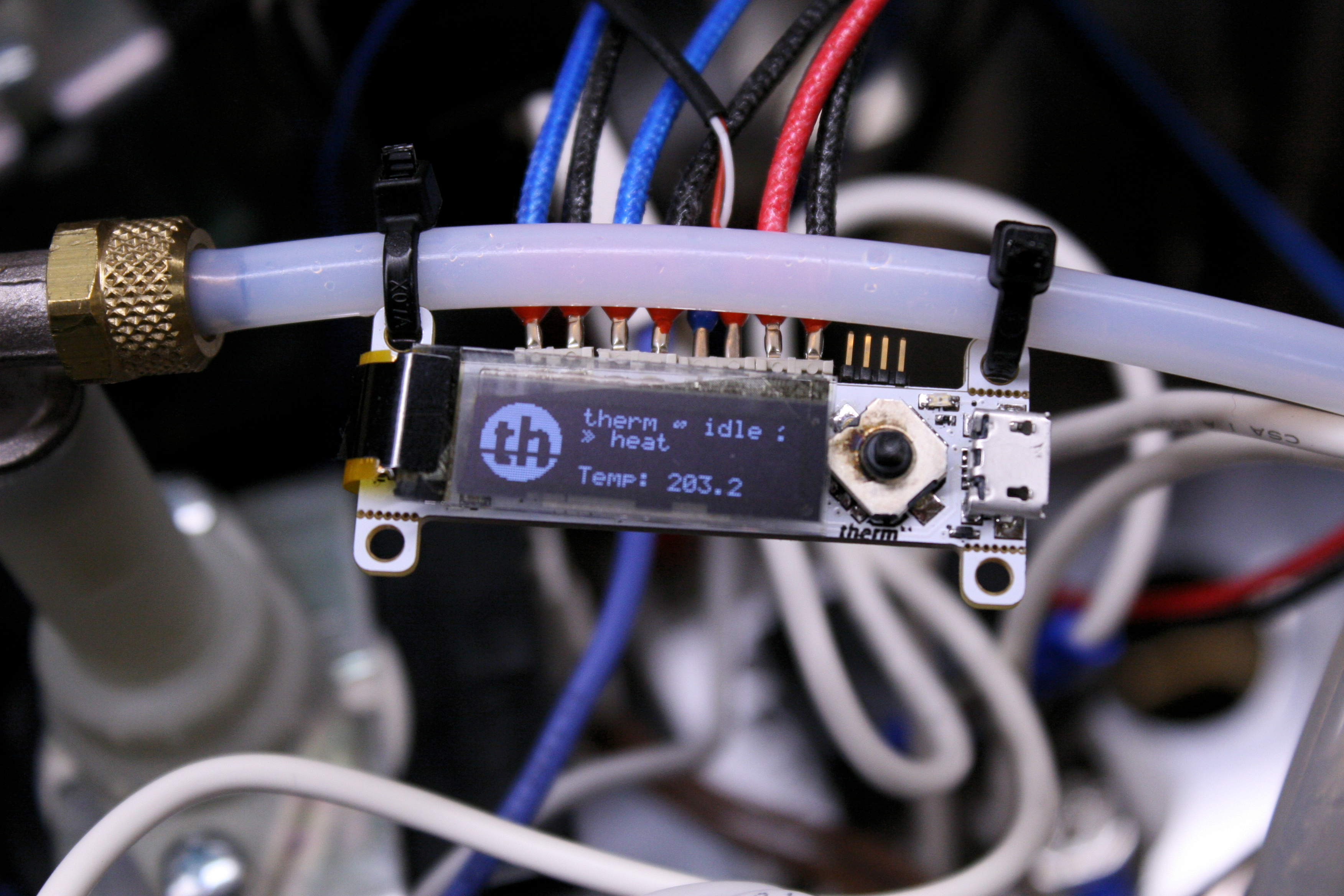
Thanks David! I ended up just zip-tying the therm module to the water line inside the top of the machine (shown in the last picture of the slideshow). This means the display is not visible during normal use, but using a “set it and leave it” approach allowed me to avoid cutting a hole in the machine for the display. You could just as easily wire the therm module to sit on top of the machine or cut a hole to mount the display in.
Really cool project! I’m hoping to brew up something similar when time allows. If you ever end up selling populated boards let me know 🙂
It’S been some time since this was posted. Have there been many changes to the PID ? I’d like my Classic GAGGIA machine to work as well as the one described to enjoy the benefits of consistent quality espresso at home. I am in the EU and the machine is made for use here. This one is a 230-240V 50Hz 1425W model made in Milan/2003. I am not familiar with much of the technology but the installation process does look pretty straight forward. Since the machine is is such good original condition I would not want to make permanent changes or modifications. I’m sure I can resource what is needed here in Germany. I’m not the person to make the THERMO part and it also sounds like it would take me some time to understand how to calibrate this. I’m an analog guy and even less of an electronics person. I am still interested in attempting the improvements described as an introduction to projects similar to this one. Keep up the good work!
I’ve been using this machine with these modifications ever since I posted this article and haven’t made any changes to the PID system yet. The modifications I made are completely reverseable, although it would take a similar amount of effort to revert back to stock after making the changes.
This all sounds like I can manage the mods. Software or openware is another thing. I’m an analog person. That may be challenging. Really, I am not a digital person or even a binary program type. I use analog equipment as much as posssible to do my work. Now we can see now my attraction to the espresso machine and hopefully easy enough modifications and tuning the PID. So i need to connect this to a computer to load it?
So Is THERE still something to build or is it possible to purchase somewhere by now or have someone buid? Regards, JT
We aren’t currently selling this controller, but it is all open source, which means the PCB design files can be downloaded, fabricated, and assembled, and the software can be downloaded, compiled, and flashed on the microcontroller. If you’re comfortable performing these steps, you should have no problem getting the controller up and running, otherwise, I would probably recommend using a commercially available kit to make these modifications.
This is a brilliant article, I’m going to use it as guidance when installing a sadly not open source PID in my Gaggia Classic.
One question, though I’m sure the answer will be obvious once I start the project: which steps exactly require soldering? As far as I can see, it’s mostly a matter of crimping terminals on to wires and connecting everything.
As far as I can remember, the only soldering in this project was attaching wires to the 5V power supply pins. Other than that, I tried to crimp everything.
Hi Matthew, I found this such a cool project that I’ve rolled the dice and tried to build the PCB and flash the firmware even though I have no experience with SMD soldering and embedded software/hardware.
After a lot of googling and troubleshooting I managed to order and fabricate the PCB, install the Arm GNU toolchain, open the source files into Eclipse and compile the binary firmware file.
However, flashing the board with texane/stlink fails due to the binary size exceeding the 64K Flash memory of the STM32F302K8U6 microcontroller. I enabled various optimization options in Eclipse but cannot seem to reduce the .bin file size further than 66KB (74KB hex file).
Anything obvious I’m doing wrong? Thanks!
Thanks for reaching out! I’m excited to hear that you took the plunge to make your own, even without much previous experience – that’s the best way to learn imo!
Regarding your issues with flashing, lets start off with the basics. Which revision of the board did you build and which software repo/commit are you compiling?
Feel free to email me at matthewreed64@gmail.com if it’s easier for you.
Thanks so much Matthew! I’ve sent you an email…
Hey,
I’m about to start this project. I had a couple questions on your process since I’m in the same boat; starting from scratch.
Did you ever figure out how to flash the microprocessor? Did you use Pogoprog or the micro USB to flash?
I’m having some trouble sourcing the exact components on the PCB. Did you get your parts SMT manufactured or did you have to solder it on?
Thanks,
CX
How is the hardware setup so that you can connect the 120V Steam switch to the Therm?
The steam switch is DPST, which means it has two separate switch circuits which are isolated from each other. I disconnected the heater wires from one of the switch circuits, and connected that side of the switch to Therm, which keeps it separate from any 120V lines.
That makes a ton of sense. Don’t know why it didn’t connect with me to do it like that last night. Instead, I was looking at opto-isolator modules and couldn’t find where you were including one. This now makes complete sense and is so obvious.
I wasn’t happy with the market PID controllers, so I’m creating my own for my Gaggia Classic Pro and this article was very helpful.
Ok, I am out of the hospital (for now) and ready to take a look at this project again. One thing came to mind that has to do with possibilities of a hot water switch to deliver a small stream of hot water through the steam wand. Since I have the time I will also add a fixed water supply to this machine providing filtered water at proper constant pressure by regulation, and an outflow tube plumbed from the tray under the head. So back to the hot watter stream possibility. Can this function be added into to the controller? regards, JT
To get hot water from the steam wand in this machine, you need to keep the solenoid closed and run the pump. The steam switch is set up to disable the solenoid when steam mode is selected, which means you can use the brew switch to run the pump and get hot water from the steam wand without making any modifications. If you want want a dedicated switch for hot water, or want to keep the machine set to brew temperature while you’re drawing hot water, there are a number of ways you could change the wiring to accomplish this. One option would be to use a DPDT switch to disable the solenoid and power the pump. Most of the options I can think of wouldn’t require any changes to the pid controller, but let me know if there’s something else you had in mind!
Hi, well done! this seems like one of the best Gaggia PIDs 🙂
What are your observation regarding intra-shot stability? How this PID performs?