
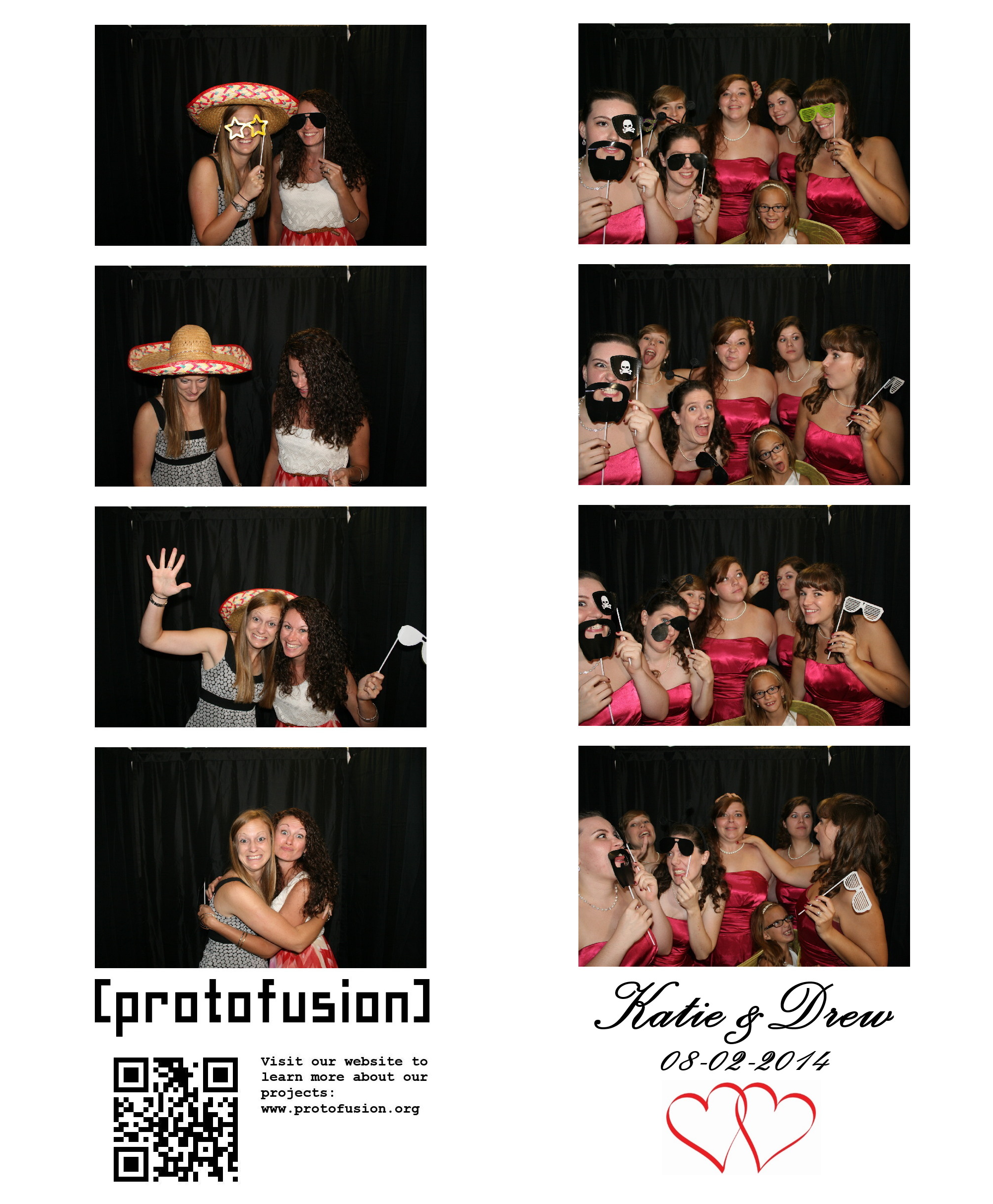
Sample photobooth photostrips
Photobooths are popular at many types of social events, including weddings, birthday parties, and school dances. However, renting one can easily cost upwards of $1000, making them impractical for many events. So when a friend mentioned wanting one for her wedding, I jumped at the opportunity to build a low-cost DIY photobooth.
To make my photobooth cost-efficient, I decided to use a thermal receipt printer to print out black and white photo strips, which eliminates the need for an expensive photo printer and photo paper/ink. I also added Twitter integration so the photobooth can tweet out every photo strip it takes, and a QR code generator that prints a link to the corresponding Twitter post on each photo strip.
The BeagleBone Black single-board computer seemed like a perfect match to power this project, and I decided to script everything in Python to keep it simple. Gphoto2 provides the camera interface, CUPS handles the printing, and Python libraries take care of everything else.
Lets get into the details of how this thing works.
Electronics
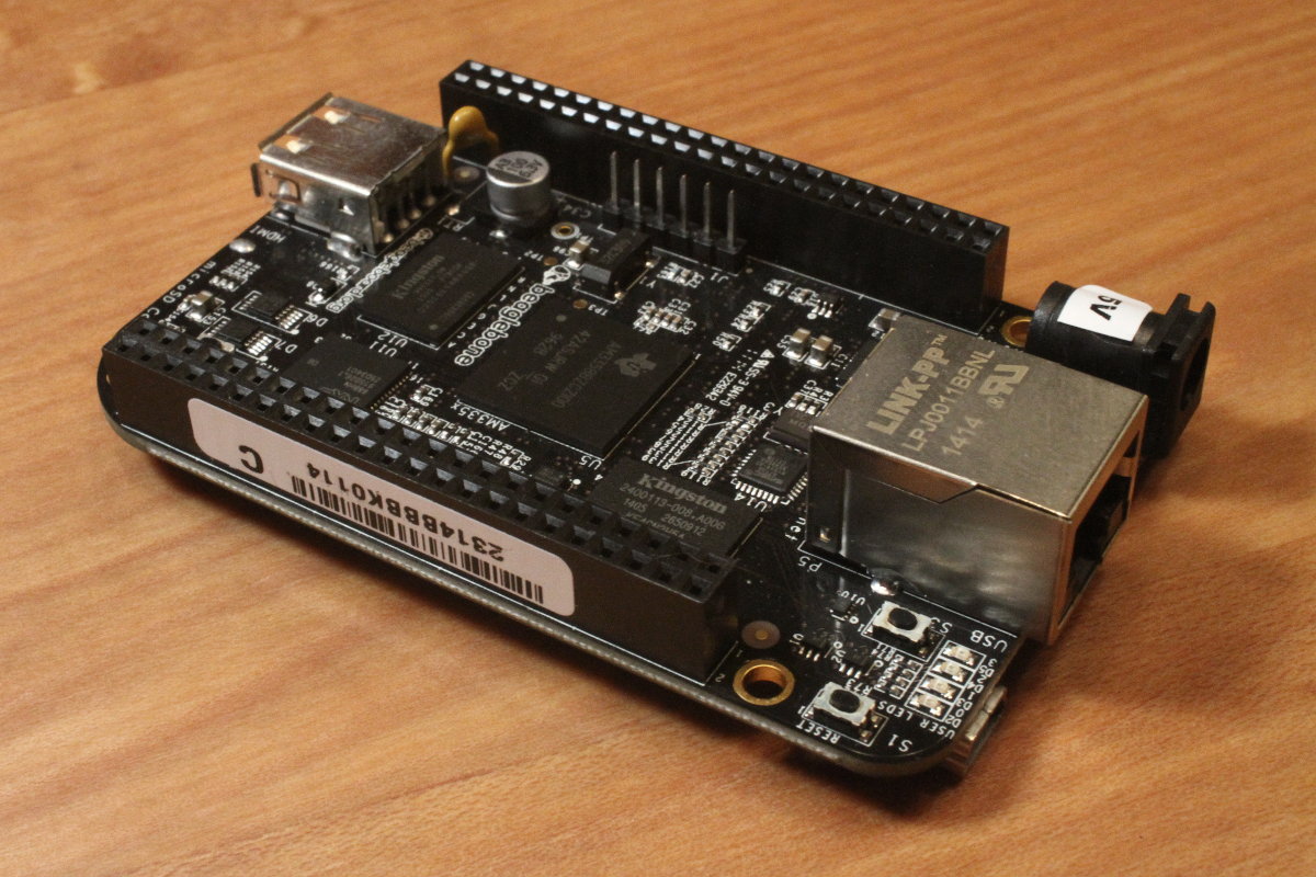
BeagleBone Black
The BeagleBone Black will boot up into a usable state without any setup required. However, I found that some gPhoto2 functions did not work with the Debian install that came preloaded on my BBB. To solve this issue, I switched to Arch Linux ARM. Instructions on installing Arch on the BeagleBone can be found here.
The basic features I wanted the photobooth to have are user input to start a photo sequence, camera control to take pictures, Twitter communication to tweet photos, and support for printing the final product. Thankfully each of these features is relatively easy to implement with Python.
I used Python 3 to allow support for some newer Python libraries. Unfortunately, this eliminated the possibility of using Adafruit’s Python GPIO library, which is only compatible with Python 2. Instead, I used the manual approach of exporting the GPIO pins to files in the /sys/class/gpio/ directory and reading the pin status values from the files. In Python, it looks a little something like this:
import io

# export pin 7
f = open('/sys/class/gpio/export', 'w')
f.write('7')
f.close()

# define pin 7 direction as input
f = open('/sys/class/gpio/gpio7/direction', 'w')
f.write('in')
f.close()

# read pin 7 status
f = open('/sys/class/gpio/gpio7/value', 'r')
status = f.read()
if("1" in status):
    # do something
elif("0" in status):
    # do something else
f.close()

# unexport pin 7
f = open('/sys/class/gpio/unexport', 'w')
f.write('7')
f.close()
The GPIO pins can be used to capture button presses and trigger the photo sequence.
The primary function of a photobooth is to take pictures, so if nothing else we’re going to have a camera in the setup. The Gphoto2 library takes care of camera integration and simplifies it down to just a few commands. The library supports thousands of camera models, so chances are your camera will work. A list of supported cameras can be found here. Since I wanted to take 4 pictures in a row with even spacing and immediately download the pictures, I used the following command and arguments:
gphoto2 --capture-image-and-download --interval=3 --frames=4 --filename /tmp/portrait%n.jpg --force-overwrite
The arguments can be modified to fit various needs—for example, saving the photos on the camera’s internal memory after they have been downloaded.
I wanted to display live view from the camera on a monitor that would allow users to see themselves as they pose for pictures, but I wasn’t able to get this working. Gphoto2 seems to turn off live view on my camera after the first picture is taken, and it won’t come back on until the camera is power-cycled. I will be working to find a solution for this issue in the future, possibly by streaming the live view video to the BBB and displaying it from there, or by replacing the camera with a high-def web cam, but until then I will live without it.
To give the user feedback when each picture is taken (in the absence of live view), I decided to turn on the camera flash, even though using the built in flash is less than optimal. Without this feedback, it is difficult to tell when each picture is being taken and when the set is finished. To minimize the blinding effect a bright flash tends to have, I turned down the flash brightness to around a 16th of its usual strength.
Because a photobooth tends to be fairly dark, and since I wasn’t relying on the flash for full lighting, I added some extra lighting to the setup. I decided to use Protofusion’s Luma lighting system to give me flexible control over the lighting through the BeagleBone Black. This allowed me to easily set the lighting levels and give some additional feedback regarding program state or errors by flashing the lights different colors. Using the Luma LED Strip Driver and an LED strip, I was able to string lighting around the top of the booth and light it with a soft, distributed light. In the absence of such a high tech lighting system, any standard light source could be used. If the light source tends to be direct and harsh, I would recommend some type of diffuser to distribute and soften it out a bit.
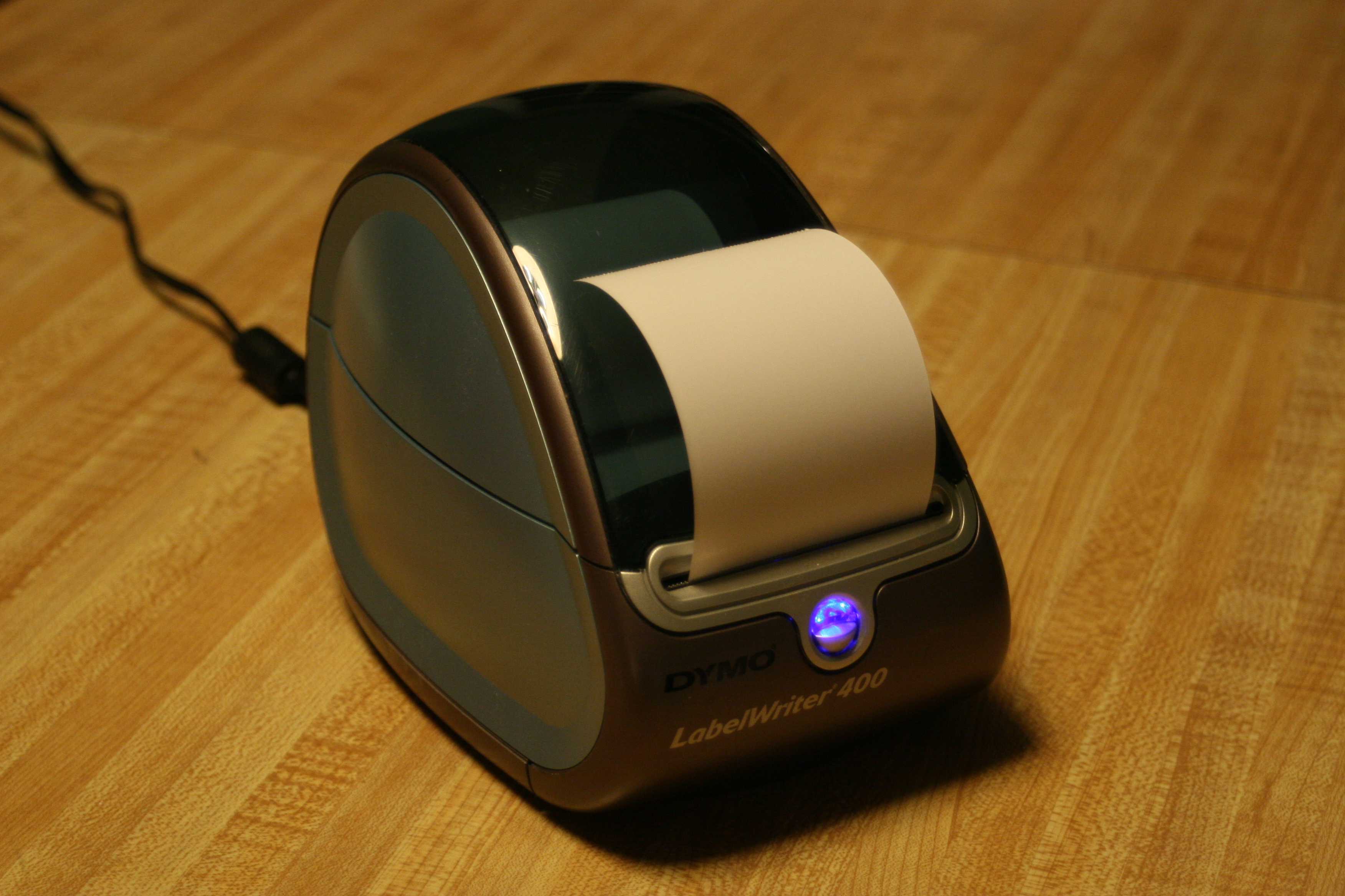
DYMO 400 Printer
I picked the Dymo 400 Labelwriter to print the photo strips because I could find it on eBay for pretty cheap, and it seemed widely used and supported. To use it with the BBB, I installed the CUPS printing system and found the Dymo driver in the Arch User Repository (I recommend Packer for installing packages from the AUR). Here is a good tutorial on installing and configuring CUPS.
To make the Dymo 400 print the way I wanted, I had to make a few tweaks. When I chose the “Continuous Feed” paper option in CUPS, it would print a large margin at the top of strip, so I tried setting a custom paper size. No matter what custom paper size I set, the printer would always print out the strip, and then print out an equal amount of blank paper. There may be a solution to this, but I was unable to find it. So the work around I used was to manually change the default printing settings for the printer, by going through the printer configuration file and changing the printable area for the “Continuous Feed” paper option. The modified file can be found below.
To format the individual photos into one photo strip, along with some text and a QR code at the bottom, I chose the ImageMagick command line image editing tool. I used the convert -append command to assemble all the photos into one image. The one problem I found here was that the large photos taken by the camera were too large for the program to combine into one with the limited RAM on the BeagleBone. Instead, I resized each of the photos and then assembled the smaller images. Since the Dymo 400 printer has a printable width of 672 pixels, I converted all the images down to that size. Here is the sequence of commands I used to assemble a photo strip:
# resize each of the pictures and add a border to make them go together nicely

convert /tmp/portrait1.jpg -sample 26% -bordercolor '#FFFFFF' -border 2x20 /tmp/portrait1.jpg

convert /tmp/portrait2.jpg -sample 26% -bordercolor '#FFFFFF' -border 2x20 /tmp/portrait2.jpg

convert /tmp/portrait3.jpg -sample 26% -bordercolor '#FFFFFF' -border 2x20 /tmp/portrait3.jpg

convert /tmp/portrait4.jpg -sample 26% -bordercolor '#FFFFFF' -border 2x20 /tmp/portrait4.jpg

# put the pictures all together and add the protofusion logo

# this is the version I tweeted

convert -append /tmp/portrait1.jpg /tmp/portrait2.jpg /tmp/portrait3.jpg /tmp/portrait4.jpg /root/protofusion.jpg /tmp/twitter.jpg

# resize the QR code

convert /tmp/qrcode.jpg -sample x245 /tmp/qrcode.jpg

# add the QR code and some text together horizontally

convert +append /tmp/qrcode.jpg /root/photoboothtext.jpg /tmp/qrblock.jpg

# add the QR code and text to the photo strip

# this is the version I printed

convert -append /tmp/twitter.jpg /tmp/qrblock.jpg /tmp/print.jpg
In order to Tweet photos, the photobooth needs to be connected to the internet. I used a TP-LINK TL-WN722N wifi dongle I had laying around, but any of the adapters on this list as well as many others should work well. The Arch Wiki details the steps for connecting to a wifi network in Arch Linux.
Twitter integration adds a fun twist to the traditional photobooth. I used the twython Python Twitter API wrapper, which simplified many of the steps. The only tricky part is authenticating through Twitter’s three step authentication process. I haven’t yet added authentication support to my script, so I just manually hard-coded in the generated keys needed. I hope to add Twitter authentication to the next iteration, and will write about that when I finish it.
To give users an easy way to find their tweeted photos, I used a Python QR code generator called qrcode that generates a QR code with a link to the posted image. The generator takes the link returned by the Twitter API and spits out a QR code which is saved and appended to the photo strip. I also added some custom text next to the QR code to explain what the QR code links to.
You can find my Python code here: photobooth.zip
You can find the cups printer config file I used here: printer_config.zip
Here is a list of the tasks (detailed above) that need to be completed to set up the full system:
- Install Arch Linux
- Install Packer
- Install Python
- Install Python libraries:
- twython
- oauthlib
- qrcode
- pyserial
- Install and configure Cups
- Install and configure printer drivers
- Setup wifi connection
- Install Gphoto2
- Install ImageMagick
Physical
The physical aspect of the photobooth was the easiest part to build, although my simple design has the potential to be greatly improved. To create the enclosure, I opted for a simple PVC pipe frame that could be quickly disassembled and easily transported. I made the enclosure 6 feet long, 4 feet wide, and 6.5 feet tall. These dimensions can be adjusted based on application, but I wanted plenty of space in mine for several people to stand and pose. So far, up to seven people at a time have successfully fit in it. The length really depends on the type of camera and focal length being used, but 6 feet seems like a good starting place. The height is also highly variable, especially if people will be sitting. But since I designed with standing in mind, I wanted to accommodate some of the taller potential users.
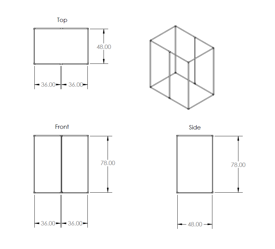
I chose ¾” PVC as a good compromise between cost and strength, and was able to find the elbow pieces I needed to assemble a cube. Here is the design I used for the frame:
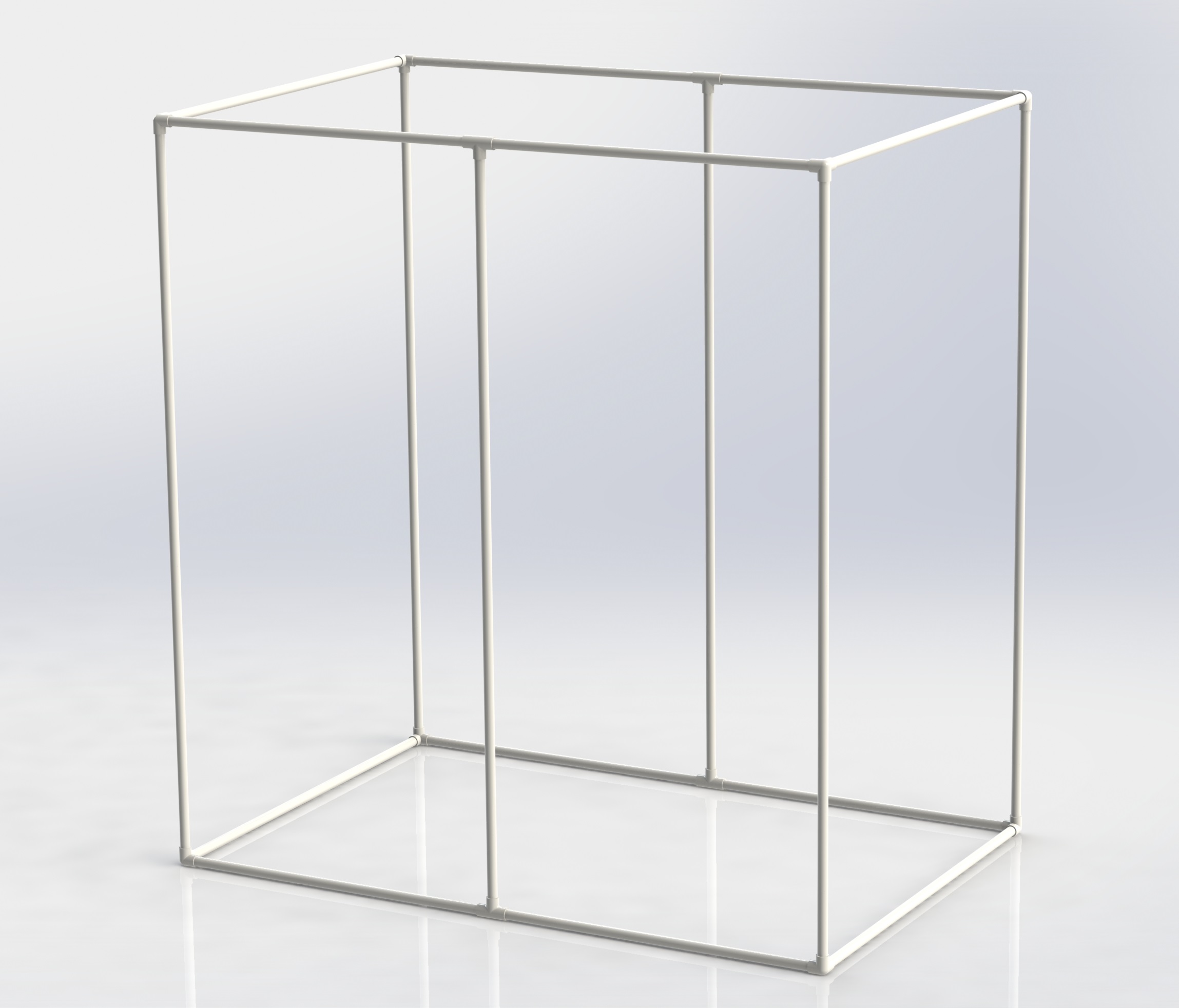
Photobooth frame made with PVC pipe
Once the frame was built, I chose curtains to cover it. Curtains are a slightly more expensive choice than some of the other options (bedsheets, etc.), but they come pre-made in various lengths, with loops in the top that make them perfect for hanging on PVC. I chose black to create a more private feel in the booth, but in hindsight, something lighter may have allowed better contrast in the photographs and prints.
When I was looking to find some sort of button to use to trigger the photo sequence, I came across a round foot pedal from a tattoo machine. This worked especially well because the booth is designed to be used standing up. However, any type of input could be used to trigger the sequence.
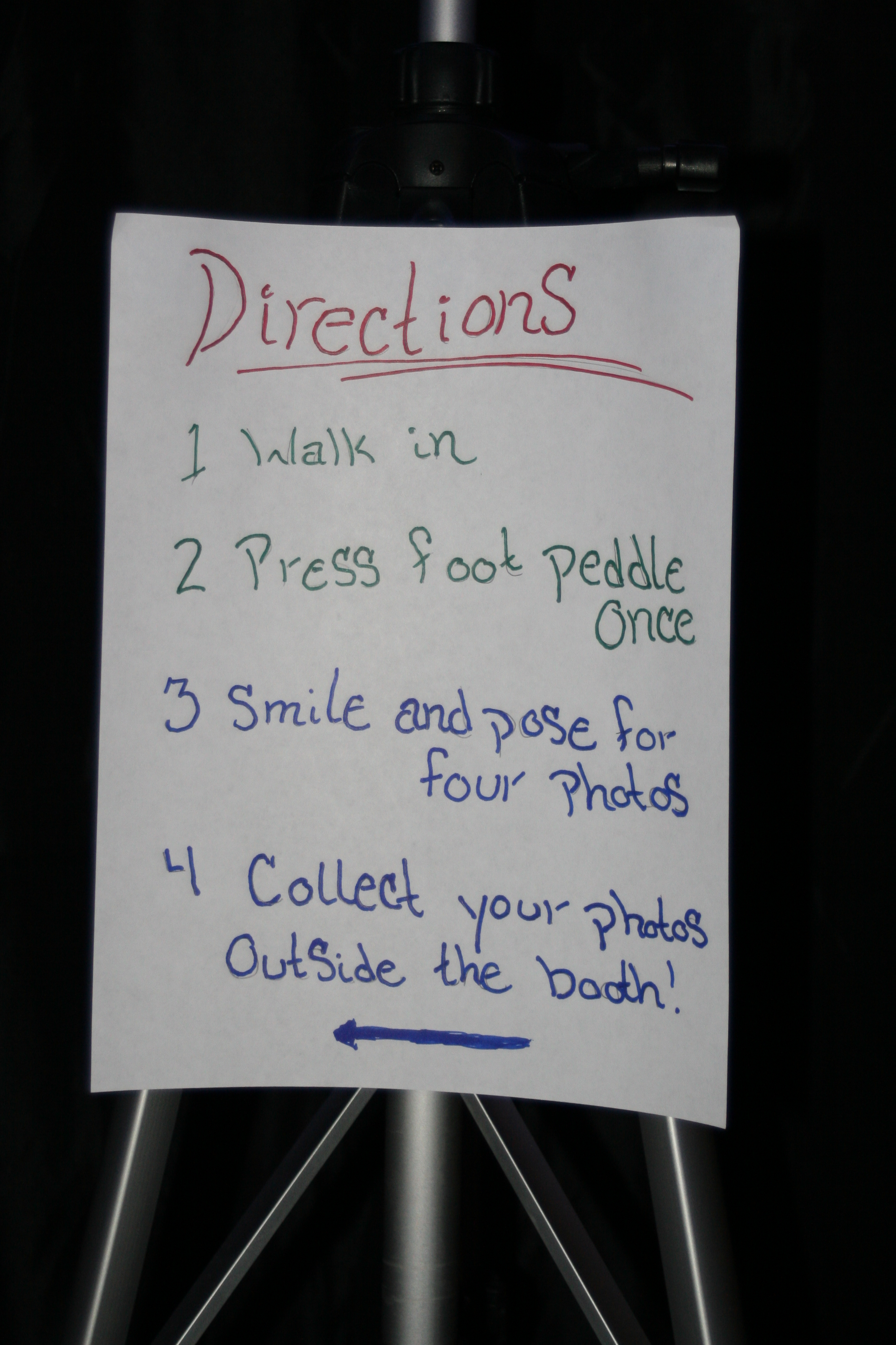
Photobooth instructions
The photobooth setup also needs a tripod, or something to hold the camera. I used this tripod and was really happy with it. Lighting is also important in a photobooth, so some sort of fill lighting would be desirable. As mentioned above, I found a fancy solution to this, but any light source should work. I also found that some people tend to be confused no matter how straightforward the interface is. Although it may seem tacky, an instruction sheet can really clear up confusion, and when creatively designed, can blend in seamlessly with the look of the booth.
A photobooth can help create spontaneous and memorable moments at any party or get-together. I hope the details here will inspire someone to build their own, because sometimes it’s more fun to do it yourself!
Materials
Here’s a list of the materials I used to make the photobooth, along with an idea of what they all cost.
- Beaglebone Black x 1 = $65
- USB hub x 1 = $15
- Wifi adapter x 1 = $18
- Thermal printer x 1 = $30
- Receipt paper x 4 = $24
- Foot pedal x 1 = $12
- Tripod x 1 = $20
- PVC pipes x 10 = $25
- PVC connectors x 12 = $12
- Curtains x 6 = $60
Total = $281
Already had:
- Camera
- Lighting
Tools:
- Hack saw
- Screw drivers
- Wire cutters
- Computer
Matthew is a computer engineer who enjoys designing hardware for embedded control systems. His hobbies include photography, gardening, coffee, and anything DIY.
Hi, Mathew this look very interesting, nad I will follow to do one for my daugthers birthday party, do you think that I can use a raspberry Pi or a C.H.I.P instead of the beaglebone?
Absolutely! The next revision of the photobooth (which hasn’t been posted yet) uses an ODROID-XU4. The only real difference between platforms would be in the GPIO interface.