
The ProtoProg is a small open source hardware pogo pin programming solution. The ProtoProg does not need a physical connector on the board, it uses surface-mount pads for signals and thru-holes for alignment. Two standard footprints are available, the smallest of which takes up very little space–only 7.6mm x 1.2mm!
Design

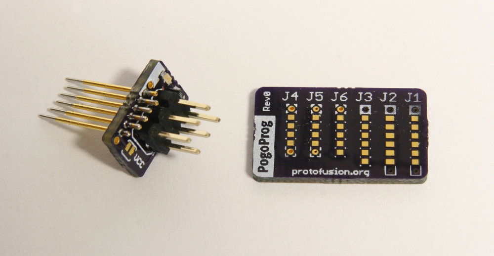
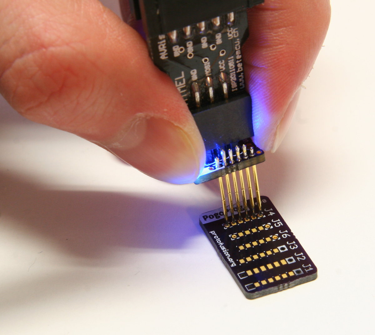
The ProtoProg was originally designed for use with AVR microcontroller programming (using 6 pins), but this design can easily be repurposed for other programmers. Several footprints are available for this programming connector as shown on the test PCB above, but only two are recommended for real-world use:
- J1 (ProtoProg Standard) – Small pads with alignment holes (8 pins required)
- J4 (ProtoProg Micro) – Small pads with alignment vias (6 pins required)
Choose the micro footprint for small size
J4 does not include any dedicated alignment holes and instead uses two of the signal lines with vias for pin alignment. The pogo pins do not go through the vias, they rest on top of the vias and “snap” into place for alignment. This footprint is very compact.
Choose the standard footprint for easier alignment
The standard footprint includes dedicated alignment holes, and requires 8 pins to be populated on the ProtoProg programming adapter. This connector takes up more lateral room, but allows for easier insertion and likely more reliable long-term use.
Assembling the ProtoProg
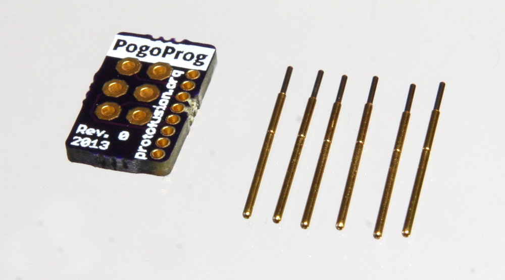
To begin, make sure you have these components:
- 6 or 8 pogo pins (depending on which footprint you want to use) [ebay]
- 2 ProtoProg PCBs (one is used for alignment) [gerbers provided below]
- Vise (recommended)
- Soldering iron and solder
First, take one of the ProtoProg adapter PCBs and solder a 6×2 pin header on the top side.
If you are using an AVR programmer, I recommend soldering the VCC solderjumper on the top of the PCB. This allows your programmer to detect target voltage and power the target (if your programmer supports this feature). You can also solder on an optional LED and current limiting resistor, which is placed on the AVR ISP VCC pin.
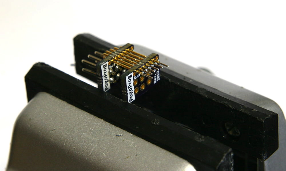
Next, take your ProtoProg board with the 6×2 pin header and a blank ProtoProg board and place them in your vise (see photo above). Carefully insert pogo pins into each hole before you completely tighten the vise. This will align the pins before you solder them.
Next, align the pins so that the two outside pins stick out about 3mm past the other pins. These pins will make contact with the alignment holes on the footprint before the rest of the signal pins.

Finally, solder each pin to the PCB. Make sure each pin makes a good solder joint with the pads, as these joints form both an electrical and mechanical connection.
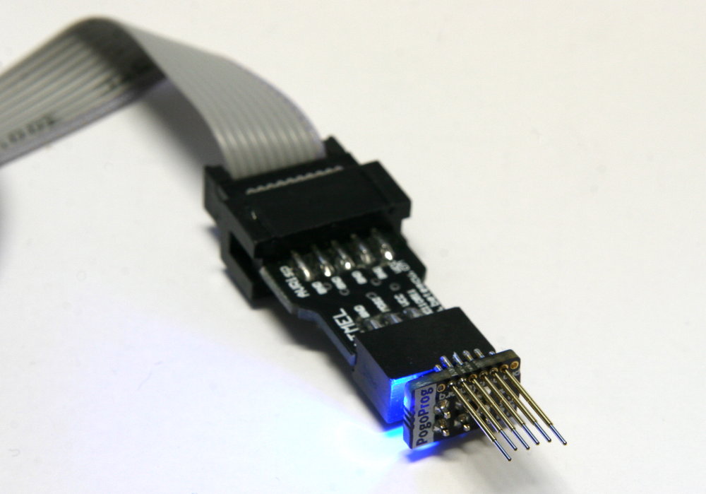
Finally, attach your programming adapter to your programmer. If your programmer is configured to power your target board, the ProtoProg LED will illuminate. If the target is self-powered, the LED will illuminate when you plug the ProtoProg into your target board.
When programming, carefully press the ProtoProg adapter on your footprint. If you are using the micro connector, make sure the two outer pins “snap” into the alignment vias before fully pressing down the connector.
If you are using the standard connector, make sure the two outer alignment pins go into the outer alignment holes before completely pressing down the connector.
Note: This project was recently renamed, but the PCBs and photos above still bear the old name.
Design Resources
- Protofusion Eagle Library (footprints for your own PCBs)
- ProtoProgAdapter v1.0 (ready-to-fab gerbers for OSH Park)
- ProtoProg Adapter v1.0 (Eagle design files)
If you have any questions or suggestions, leave a comment below or send a message through our contact page.
Ethan is a computer engineer and open source hardware/software developer from Michigan. He enjoys AVR and linux development, photography, mountain biking, and drinking significant amounts of home-roasted coffee. Find out more at ethanzonca.com.
Would you mind googling before you name your next project?
http://ubertooth.sourceforge.net/hardware/program/
Pogoprog is a spring pin FTDI board developed as part of the Ubertooth project. It can be used to program LPC17xx and many other microcontrollers with ISP.
Sorry about that! This was an internal project we were testing on one of our boards, and I just stuck with the random name we came up with. I added a note to clarify at the beginning of the post with a link to your site.
Edit: Just did a little find/replace on this page. The images don’t match the text, but that shouldn’t cause too much trouble 😀
wow, that’s really disappointing. I second this – I’ve seen “Pogoprog” before and I was surprised that this website isn’t actually it. It was the ubertooth page I was thinking of.
PLEASE use a unique, new name. If you “accidentally” use the identical name as someone else, at LEAST make sure you’re not naming and selling a nearly identical product.
Stay tuned! Next week we will demonstrate our new Interchangeable Bootloading Module, which will will call “IBM” 😉
It was super nice of you to change the name so quickly. A++ WOULD BERATE AGAIN 😉
Excellent work, even J1 makes the standard programming pins look pre-historic. A next step might be to add some method to keep the programmer in place. Magnets perhaps.
PS, the comments about naming seem a little harsh. Granted someone else is already using the pogoplug name, but given a programmer based around pogo-pins, it’s not as the though that name is worthy of an award for originality.
P50 J1 for pogo-pin?
I want to build one for JTAG/SWD used in most of Cortex-M micros.
I am still struggling there is not a standard pinout for reduced connectors.
Min: VSS/DIO/CLK/
Max: VSS/VDD/DIO/CLK/RST
Segger defined a standard pinout as “niddle kit”, which use 5×2 pinout.
For SWD you can get away with VSS/DIO/CLK, but some programmers want to sense the target voltage so you might want to use Vdd as well. I haven’t had a need for reset and the boundary scan SWO pin, but they are needed for some use cases.
This is an interesting project. I could use it with a project I’m currently working on. I was including space for a 6-pin programming header but using pogo pins I can save some board space.
I used gerbview under Linux to look at the gerbers in the PogoProg-RTM1.zip file. It shows the middle two pins of the 6-pin header as being offset from the other 4 pins.
The other thought I had is whether it would be better to include two other holes in the corners on the side opposite the row of pogo pins to use some header pins as a way to help stabilize the two boards in relation to each other? It would minimize the chance that the pogo pins would get damaged if the open edges of the two PCB’s ever got squeezed together.
Hey Kevin,
The two middle offset pins are a feature that should friction-fit the 6-pin header to make soldering easier. It may look a bit weird, but it works great!
Adding additional holes to stabilize the board sounds like an interesting idea, let me know how it works if you end up trying it!
Also, I currently use an updated version of this design with only 4 pins for SWD-capable microcontrollers. It’s essentially the same thing but scaled down to 4 pins and without any keying pins.