
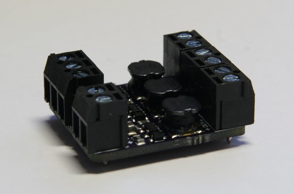
The PicoBuck is a small and inexpensive 3-channel LED driver. It employs constant-current buck driving which approaches an efficiency of 95% (theoretical).
Now available from SparkFun Electronics!
Documentation
More detailed documentation will soon be available on the wiki!
Capabilities
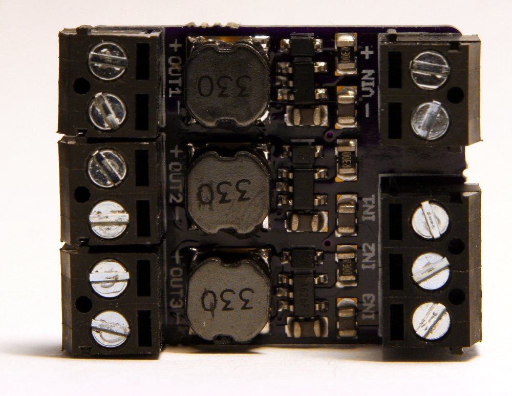
The PicoBuck supports a wide range of input voltages (6v to 20v) which may be connected to the VIN header. It has three inputs for each driver channel, labeled IN1, IN2, and IN3 which may be driven with standard 3.3v or 5v logic. LEDs are connected to the outputs of the driver, OUT1 through OUT3. Each channel of an RGB LED must be connected to the driver separately: this driver, like most buck drivers, does not support common-anode or common-cathode RGB LEDs.
Each channel of the PicoBuck can drive an LED at 350mA on the standard model. The driving current is set by a small current sensing resistor populated on the board. If you need to drive LEDs at higher or lower currents, just swap out the current sensing resistor to achieve your desired current. You can calculate the value of your current sensing resistor with the AL8805 spreadsheet.
Usage
Digital Mode
To use digital drive mode, apply a standard 3.3v or 5v PWM signal to any of the 3 inputs. This method gives good brightness resolution over the entire range of brightness when using 8 to 10 bit PWM.
Analog Mode
To use analog mode, apply an analog voltage between 0v and 2.5v to any of the 3 inputs. This analog voltage controls how much current the LED is driven at, up to the current set by the current-limiting resistor. Note that the analog method is not effective for the last 20% of current—at this point, the current drops to zero.
Alternatively, you may employ a compound approach using analog dimming for high brightness and PWM dimming for low brightness. This method achieves optimal brightness resolution with minimal flicker, but is more challenging to implement in software.
Availability
The PicoBuck is available for purchase through SparkFun Electronics. For the adventurous, the source files are available from the SparkFun product page so you can build your own!
Resources
- Bill of Materials
- Schematic (SparkFun variant)
- Eagle Files (SparkFun variant)
Ethan is a computer engineer and open source hardware/software developer from Michigan. He enjoys AVR and linux development, photography, mountain biking, and drinking significant amounts of home-roasted coffee. Find out more at ethanzonca.com.
Wow that looks like a really minimalist design.
I’m looking for a similar design but one that can take 9 to 36 volt input voltage to drive a bank of rgb LEDs.
Is this design open source or closed? If open I’m keen to see the schematic… 🙂 if not – never mind but congratulations on producing something beautiful.
Hey! This design will be open-source as soon as it’s available for purchase. Assuming our official proto run goes smoothly (it’s out for fabrication right now), we’ll start a production run and have these boards up for sale soon!
For your specific application, how many LEDs are you planning on driving, and what wattage? We’re doing some work on an RS485-networked node for controlling multiple high-powered LEDs with a slightly modified driving circuit for higher voltage/power.
Open Source – that’s good to know. I salute your endeavours. Unfortunately I’m often stuck with the vagaries of a commercial enterprise that aren’t so open.
We will need to drive about 200 PLCC6 RGB LED’s in a small enclosure (cast in water clear semi rigid Polyurethane). Power will be either 12V Lead Acid or 24V IRL about 9 v for depleted cells or 30v++ for cells full, or straight from the 24v charger.
The application is a Navigation Buoy used offshore with 6 nautical mile visibility. Control will be from a separate micro controller and I’m tied between a multi channel DAC or pwm. The colour will indicate the Buoy status, the navigation buoy will flash morse code depending on what it is marking. Current application is a morse “U”.
I guess my real question was the 5 pin IC – I wondered what it is – my guess was a comparitor/driver running a bang bang buck circuit comparing the voltage across the LED shunt to the input integrated voltage.
I’ve just never seen a comparitor capable of driving 500mA… Maybe I need more homework 🙂
My current solution is WAAAAAY more complicated involving PIC controller, PWM’s, A/D converters with feedback… I liked the beauty of your solution.
The RS485 is interesting, but maybe for home lighting rather than my application.
Thanks for replying – makes me feel the web is alive…
Glad I can help! To give you a hint, my design is actually way simpler than you might think: I’m using a dedicated buck LED driver IC. There are a ton of good driver ICs in the sot23 and sot25 packages, but they’re pretty expensive. After lots of research on various driving methods, I landed on the AL8805, a fairly new chip from Diodes that’s only about $1 in small quantities. If you’re running the channels of groups of these LEDs in series, this chip could work well for you. Just make sure to size your inductor and diode appropriately! The Diodes inc. website has a nice spreadsheet to help with component choices, output voltage ripple tolerance, etc. Good luck! Feel free to email me at admin@protofusion.org if you have any more detailed questions, I’m glad to help.
That is the first useful LED driver chip I’ve seen – a tiny package and pretty cheap.
We have some PCB’s on the way with this driver on one side of the board and x36 PLCC6 RGB LED’s on the other – on a PCB 3″ x 1″. The idea now is to use 6 of them to cover a 360 arc.
I’ll post some PIC links once we’ve built up the PCB’s.
Thanks – it was a superb component tip!
I’ve ordered a couple of these through SparkFun, and provided all goes well with ramping them up to 700ma-per-channel (as per our Twitter conversation) I’m going to be designing some donught-shaped boards with 12 PicoBuck circuits on it, to power each colour in 12 high powered RGB LEDs.
Do you have a BOM available, so I can be sure to use all the same parts, so I don’t end up with any surprises?
Cheers!
i was looking at your bill of materials, because i was wondering if this circuit could be driven with 24v.
because i need to make it work with an already existing architecture.
you are mentioning higher voltage caps. would one also have to use a diode with a higher “Voltage – DC Reverse” ?
thx
Ethan,
I promised a photo and failed to deliver – anyway – here it is finally. Coupled with a cheap source of RGB LED’s it became a nice little board.
https://twitter.com/SeismicStuff/status/494163774753218561
Thanks for the component inspiration!
And to give back something in return the RGB LED’s I found can be purchased reasonably cheaply on ebay from…
http://www.ebay.co.uk/itm/1000PCS-5050-3-Chips-RGB-SMD-SMT-LED-PLCC-6-20lm-/221185976642?pt=LH_DefaultDomain_0&hash=item337fb62942
Rgds,
Craig
Nice work! Glad you were able to make good use of the driver IC, that looks like a really clean and simple design.
Hi Ethan,
how is the low dimming performance of this?
i am searching for a driver that can dim down to 0 without a ‘jump’ in the low end range..
my requirement is a single high-power led – 350mA (optional up to 700mA) – led forward Voltage is about 2V to 4V. (red.. blue/white)
second requirement for me is a simple design that i can build by hand soldering / were the components are easy to get in low quantities…
😉
if you have some tips on this let me know 🙂
i will order one of your designs by my next shopping tour by one of the SparkFun resellers..
sunny greetings
stefan
The low-end dimming is surprisingly good. I have typically driven it with 8bit PWM so it’s a bit jumpy on the low end, but with 16bit PWM you will have really smooth low end dimming.
If you’re using an Arduino, just remember that the analogWrite() function typically does 8-bit PWM. You can directly write to registers and get 16-bit PWM working, or use a library.
I’ve been using these 16-bit PWM controllers from Adafruit:
https://www.adafruit.com/products/1455
for driving PicoBucks and have gotten really good low-end dimming.
Thanks for your reply 🙂
your board is in the shopping cart..
@Derek i will try this- i have the 16Bit board at my desk 🙂
how do you connected it? – the outputs of this are constan current if i remember right..
at the moment i have tested a design with a
RECOM RCD-24-0.35 (http://www.recom-international.com/pdf/Lightline/RCD-24.pdf)
in combination with
Adafruit 16-Channel 12-bit PWM/Servo Driver – I2C interface PRODUCT ID: 815 (https://www.adafruit.com/products/815)
i experimented with all possible combinations of different dimming options-
1. Analog
2. PWM
3. MOSFET PWM (short over led see example on page 4 http://www.recom-international.com/pdf/Lightline/RCD-24.pdf#page=4&zoom=170,-123,404)
if i have some time i will write collect the results and write it down..
i used only one 12-bit driver – this was set to 1kHz.
so my Analog Voltage was generated with a big RC-filter out of the 1kHz PWM….
Analog+MOSFET PWM is not working –
best result was to use PWM in high..midlow range
and for the low end use analog.
its a bit tricky to map this to a continuous ‘linear’ input range…
thanks for the nice work – i will test it out.
sunny greetings
stefan
Stefan,
I’ve tried using that same 16-channel 12-bit chip/board for LEDs too, but without much luck.
I forgot about the constant-current output part of the TLC59711. I had to go check my boards to see what I did when I used it with the PicoBucks. 🙂
I build little adapter boards with a 10K pull-up resistor on each of the outputs from the TLC59711 chip. I’m not an Electrical Engineer though, so I don’t know if that’s the best way to do it or not. Maybe Ethan will chime in with some advice. 🙂
Awesome design, just wish it had a i2c interface on it.