
This project uses the open-source i2c RGB LED controller firmware “cyz_rgb” to create a modular high-power lighting network. The network is controlled by an Arduino, which scans the network for nodes controls them autonomously with onboard scripts, manually via serial console control, or over the serial computer-control interface for interaction with programs on a host machine.
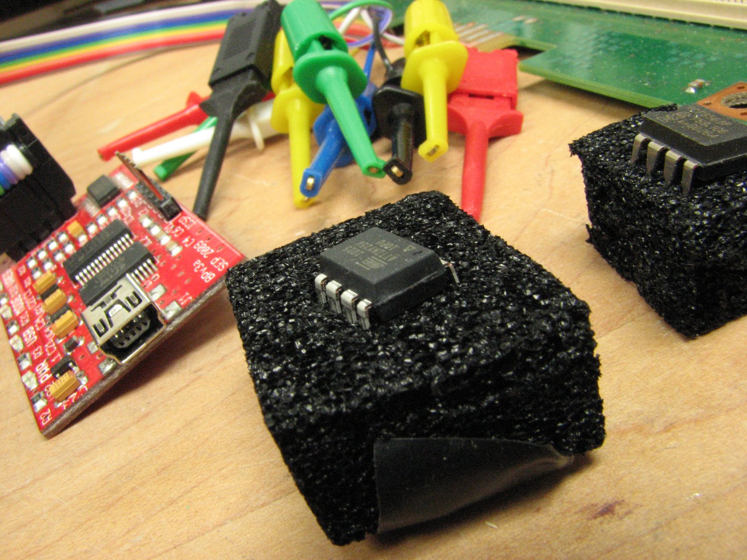
Node: BlinkM Clone
Hardware
Each node consists of only a few inexpensive components. The total cost of each node, not including shipping or bulk discounts, is around $5.50. If you order more than 3 of the 3W LEDs, the price drops drastically ($2.74 per LED and lower.
- ATTINY85 – $1.82 – Cheap, small footprint, plenty of memory.
- 3W RGB LED from DealExtreme – $3.35
- NPN Darlington transistors (only $.04 from Mouser!)
- 10uF decoupling capacitor
- Current-limiting resistors for each LED (must be 2W+ rated!)
- Optional: Pin header, screw terminal, reset switch
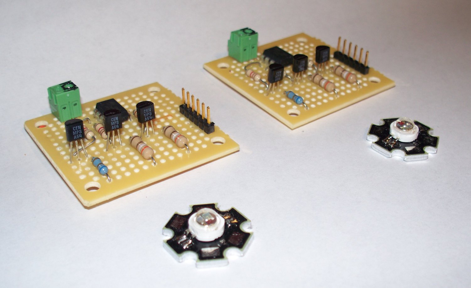
Initial Prototype on protoboard (resistors have been upgraded to 2W in the final boards)
The initial prototype node boards are shown below. These nodes include non-standard programming headers, screw-terminal power connectors, and incredibly under-rated resistors (1/4 watt for the red LED resistor!). 2W+ rated resistors are necessary if you are using a 3W+ LED. I would also recommend adding terminals for the clock and data lines, unless you want to run ribbon cable between the ICSP headers of each board which, conveniently enough, breaks out the needed power and data lines.
Controller: MNLC
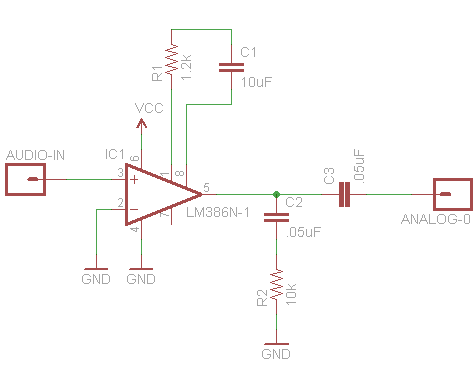
The controller for the network of i2c-connected nodes is an Arduino running MNLC. This sketch provides a simple serial terminal for manually communicating with the network of nodes, and also provides a non-interactive serial mode for host computer control. Included for testing is some code from jarv.org which reads an analog audio signal and cycles the network of LEDs through various patterns based on the amplitude of the incoming signal.

Fully assembled prototype board with proper resistors
Build your own:
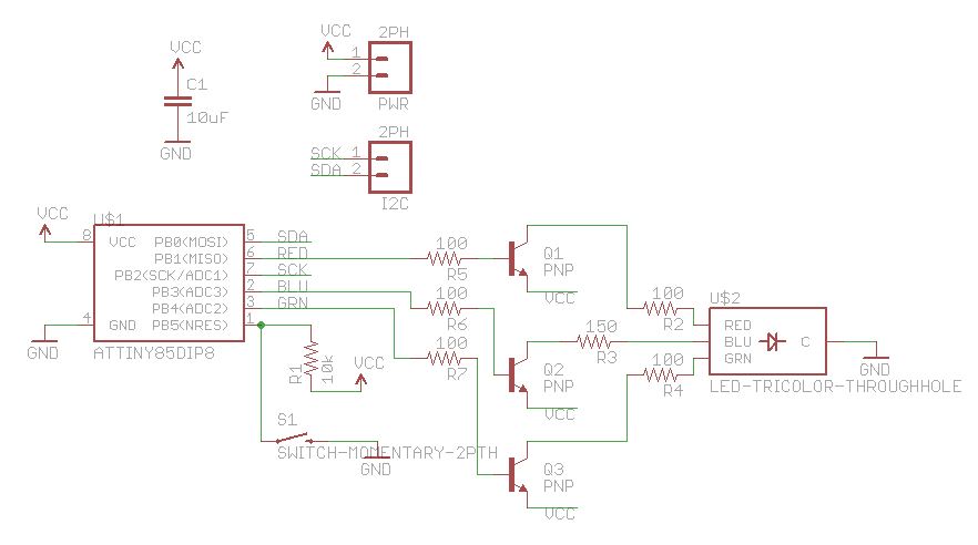
- Assemble node(s) as shown in schematic above
- Connect programmer to each node and flash ATTINY85 chips with cyz_rgb_slave firmware
- Unset the divide clock by 8 (DIV8) fuse on each node
- Assemble audio input circuit (if needed) and flash Arduino with MNLC
- One at a time, connect each node to the Arduino
- Once the node is connected, enter the interactive serial interface and use the “i” command to set a unique address for each node.
- Daisy-chain clock and data lines of all nodes to the Arduino, add pull-up resistors on both the data and clock line, and run MNLC sketch
Additional information on the construction of the final design and some notes about scaling this project up to a 12-node network with considerable distance between nodes will be added in the near future.
Ethan is a computer engineer and open source hardware/software developer from Michigan. He enjoys AVR and linux development, photography, mountain biking, and drinking significant amounts of home-roasted coffee. Find out more at ethanzonca.com.
Where did you find those pin assignments? I believe you may have the blue and Ed pins swapped. If you built this circuit, the start up sequence would be out of order, and color mixing would seem really odd.. Have you noticed this?
Looks like you’re right! Those pins do appear to be swapped on the schematic; thanks for the catch. I’ll post a fixed schematic shortly. Somehow I must have used the correct pins on my prototypes, since color mixing works properly on them.
I’ve also fabbed a PCB for this project, they just came in the other day so I have yet to test them. If the design doesn’t need any additional tweaks, I’ll post up the Eagle project if anyone else wants to order a copy (they’re just over $1 per board if ordered with Laen’s PCB order).
http://ethanzonca.com/tmp/tinyRGB-bottom.jpg
What’s funny is i built mine from the schematics on the blinkm data sheet, so i was wired up correctly the first time.. I didn’t know the blue element in my led was fried… I then found your site and said “Ethan seems to always know. I did this wrong!” so re soldered my connections according to your diagram, and somthing was still not right.. Out came the breadboard… I don’t know why I always prototype with solder and wires!!! Thanks for the board layout!