
The SSD1306 is an OLED display made with SPI and I2C interfaces. With a simple Python library I adapted (a modified version of py-gaugette), it is easy to render text, images (from bitmaps of pretty much any format), progress bars, etc. This guide is a bit on the long side, but should walk you through the whole process.
Unloading the capes
To use the SPI port, you first need to unload the HDMI virtual capes. Just echo a dash and the number of the virtual cape you want to remove to the slots file, as shown below:
# cat /sys/devices/bone_capemgr.9/slots
 0: 54:PF---
 1: 55:PF---
 2: 56:PF---
 3: 57:PF---
 4: ff:P-O-L Bone-LT-eMMC-2G,00A0,Texas Instrument,BB-BONE-EMMC-2G
 5: ff:P-O-- Bone-Black-HDMI,00A0,Texas Instrument,BB-BONELT-HDMI
 6: ff:P-O-- Bone-Black-HDMIN,00A0,Texas Instrument,BB-BONELT-HDMIN
 7: ff:P-O-L Override Board Name,00A0,Override Manuf,BB-UART5
 8: ff:P-O-L Override Board Name,00A0,Override Manuf,BB-UART2
# echo -5> /sys/devices/bone_capemgr.9/slots
# echo -6> /sys/devices/bone_capemgr.9/slots
# cat /sys/devices/bone_capemgr.9/slots
 0: 54:PF---
 1: 55:PF---
 2: 56:PF---
 3: 57:PF---
 4: ff:P-O-L Bone-LT-eMMC-2G,00A0,Texas Instrument,BB-BONE-EMMC-2G
 7: ff:P-O-L Override Board Name,00A0,Override Manuf,BB-UART5
 8: ff:P-O-L Override Board Name,00A0,Override Manuf,BB-UART2
Load SPI overlay
Download spimux.dts and generate a dto file to load into the kernel overlay:
- Generate the code
dtc -O dtb -o BB-SPI1-01-00A0.dtbo -b 0 -@ spimux.dts
- Copy to firmware dir
cp BB-SPI1-01-00A0.dtbo /lib/firmware
- Load on demand
echo BB-SPI1-01 > /sys/devices/bone_capemgr.*/slots
Check results
You should now see the SPI cape loaded in the slots file and device nodes should be present at /dev/spidev*
# cat /sys/devices/bone_capemgr.9/slots
 0: 54:PF---
 1: 55:PF---
 2: 56:PF---
 3: 57:PF---
 4: ff:P-O-L Bone-LT-eMMC-2G,00A0,Texas Instrument,BB-BONE-EMMC-2G
 7: ff:P-O-L Override Board Name,00A0,Override Manuf,BB-UART5
 8: ff:P-O-L Override Board Name,00A0,Override Manuf,BB-UART2
 9: ff:P-O-L Override Board Name,00A0,Override Manuf,BB-SPI1-01
If you don’t see anything here, check the output of dmesg for any errors.
Wire stuff up
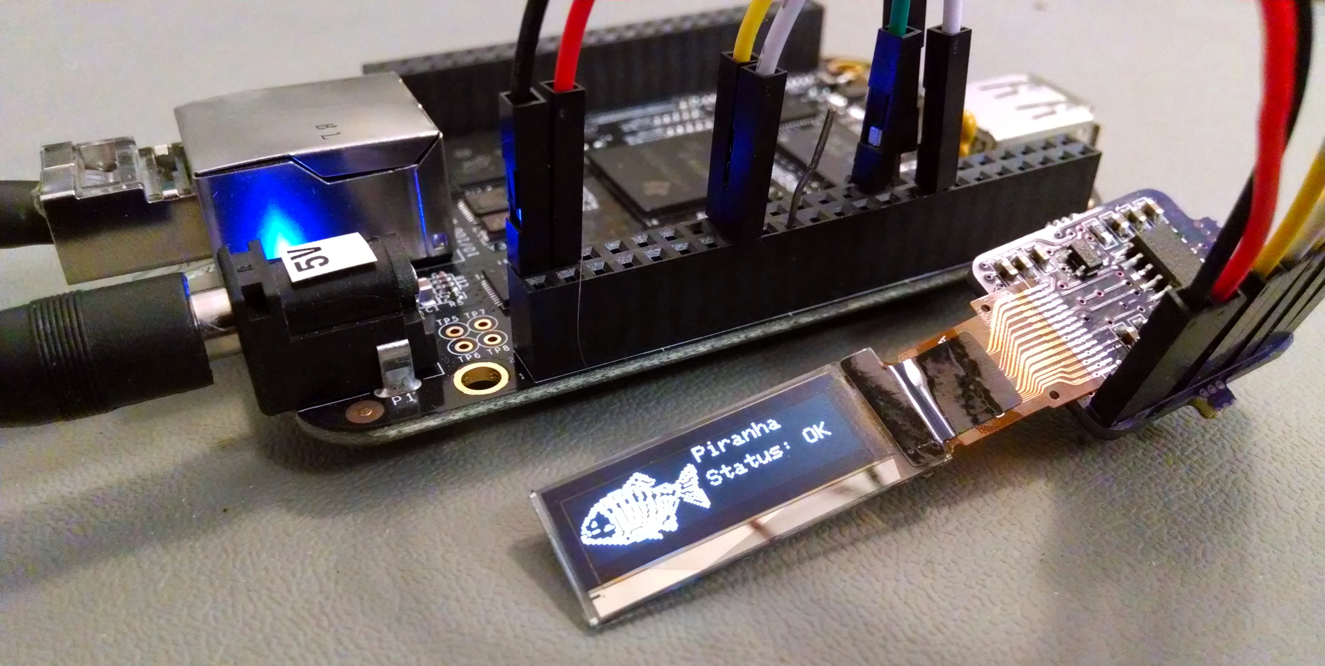
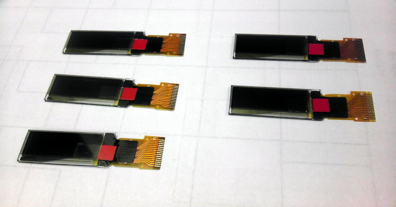
You can connect a SSD1306 to the BeagleBone Black with one of Adafruit’s breakout board, or with your own PCB design (you can use the footprint from Adafruit’s open-hardware design files).
- P9_1 – GND
- P9_3 – Vcc
- P9_13 – Data/CMD
- P9_15 – Reset
- P9_17 – Chip select
- P9_18 – Master out / slave in
- P9_22 – Clock
Install Python Libraries
You’ll need a few supporting libraries to make everything work:
- py-spidev
- adafruit-beaglebone-io-python
- python2-ssd1306-bb (the actual OLED display library)
If you’re running Arch Linux, just install python2-ssd-bb from the AUR with your favorite AUR helper like packer, and all dependencies will be pulled in automatically.
packer -S python2-ssd1306-bb
On an Angstrom-based system, you can use opkg to install the dependencies:
opkg update
opkg install python-pip python-setuptools python-smbus
pip install Adafruit_BBIO
pip install spidev
Run the Test Script
In the python2-ssd1306-bb/samples folder, run ssd1306.py. This file will show some test patterns on the screen. If you installed from the AUR and don’t have the test script, you can download it here.
If you do not see the test patterns on your display, double-check all of your connections (make sure you don’t mix up power and ground!). Otherwise, you can move on to using the library from your own code!
Using the Library
Want a progress bar?
Just call the draw_progress function with position, width, height, and the desired percent. Call the function again with a different percent value. to update the progress bar. Percent values are numbers 0-100. This function isn’t very well-tested yet, please comment if you encounter problems!
draw_progress(self, percent, x, y, width=128, height=5):
led.display()
Want to render an image?
Make sure you scale your image and convert to black/white first! All standard image formats are supported.
    led.clear_display()
    led.draw_image("/home/jsmith/logo.png", x, y)
Want to render some text?
led.draw_text2(x, y, 'Hello World', size)
Refer to the readme on BitBucket for an up-to-date overview of the library, or take a look at the test script code. If all goes well, you should be able to get results like this:
The person who wrote py-gaugette also ported his library to BeagleBone Black, although it uses a different approach for SPI communication and doesn’t have progress bars / image rendering (yet!).
Ethan is a computer engineer and open source hardware/software developer from Michigan. He enjoys AVR and linux development, photography, mountain biking, and drinking significant amounts of home-roasted coffee. Find out more at ethanzonca.com.
can any of this be done over the i2c connection, or its best to do SPI
SPI is typically faster, but I2C is super convenient and uses less pins. Definitely limits the FPS that you can render though, might not be the best choice for applications that need high update rates.