
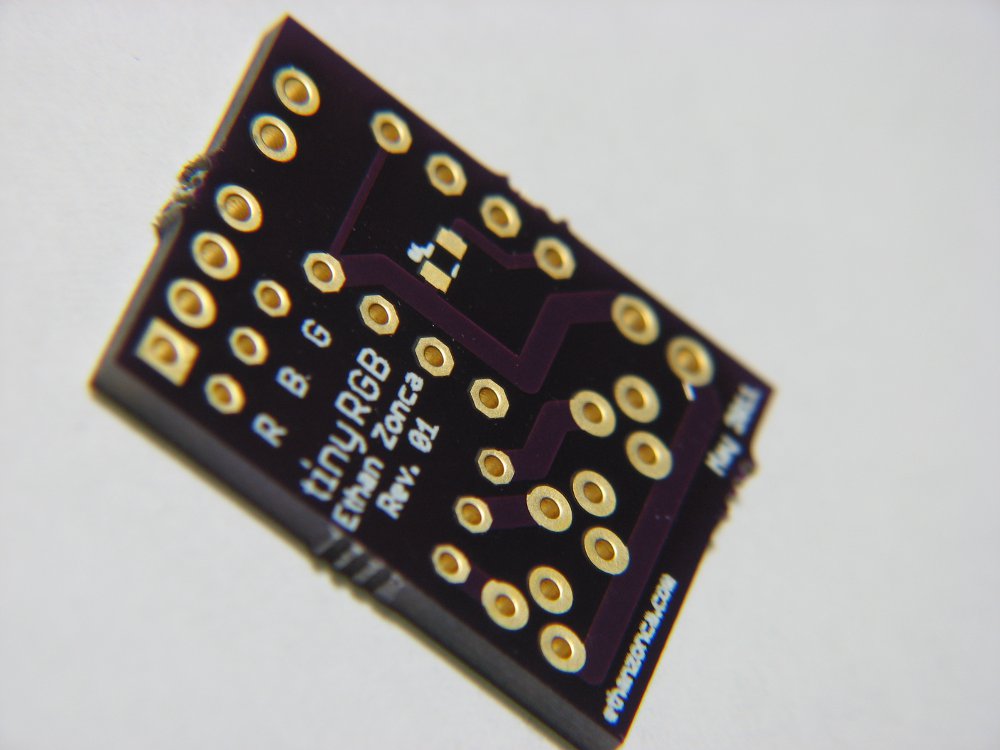
tinyRGB is a minimalist blinkM-compatible high-current i2c RGB LED controller consisting of only 10 basic components. The board is small and inexpensive, can be fabricated for as little as $1/board, and can easily be assembled by hand with a total component cost of around $3.
tinyRGB runs the cyz_rgb firmware, providing a simple interface that is completely compatible with blinkM commands.
This board is designed to run on 5v, which is also exposed on the LED output header. However, this board can easily be used to drive LEDs at higher voltages by providing a higher voltage to the common cathode of the LED.
Parts:
- PCB [$1]
- Pin Headers (if desired)
- 3x 2N6427 1.2A / 40V NPN Transistor [$.04, mouser]
- ATTINY85 PDIP [$1.82, mouser]
- .1uF 0805 decoupling capacitor (optional) [$.06, mouser]
- 3x 0805 Surface-mount 1k resistors [$.04, mouser] (yes, you really can solder them with a fat wedge tip!)
- 3x current-limiting resistors matched to your LEDs
Total cost: ~$3, plus the cost of your LED and current-limiting resistors.
For firmware installation and setup instructions see the “build” section of Multi-Node Lighting.
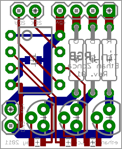
Board and schematic downloads are included below. Note that the board is a bit rough around the edges (figuratively), and could use some improvement. Drop comments below if you have any suggestions.
Downloads:
Ethan is a computer engineer and open source hardware/software developer from Michigan. He enjoys AVR and linux development, photography, mountain biking, and drinking significant amounts of home-roasted coffee. Find out more at ethanzonca.com.
Hallo, I appreciate the open source design.
I have one question though: the LED is a common cathode as far as I can see but the design seems to ask for a common anode led. also the sentence “this board can easily be used to drive LEDs at higher voltages by providing a higher voltage to the common cathode of the LED” seems confusing to me since I would imagine that on ground you always supply your ground and the anode could be a higher voltage?!
Maybe you can help me out with this!
Thanks.
I agree design suggest common anode.
Who did you use to make your PCB?
I used Laen’s PCB order, the boards are great quality for the price, and turnaround is pretty quick: dorkbotpdx.org/wiki/pcb_order
Hey,
do you have a licence for tinyRGB? e.g. CC-BY-SA? I would like to share your design. I ordered some from OSH-Park und I’m currently in the making of a new firmware for it (BlinkM compatible).
Hey, thanks for asking about licensing–I totally forgot to add a license to the repository. TinyRGB is now under the CC-BY-SA, the license file has been added to the repository (see link below).
Keep me posted on your project! I’ve been thinking about making this board all surface-mount along with a few other changes.
By the way, check out the cyz_rgb firmware if you don’t want to write your own, or if you want some ideas for how to code your firmware. The source code is fairly complex, but the way he uses the timers is interesting: http://code.google.com/p/codalyze/wiki/CyzRgb
License File:
http://protofusion.org/hg/mnl-hardware/file/6504c1714d6a/i2c-node/license.txt
Good luck!
Thanks!
I was a bit afraid of soldering the smd parts. Last week I soldered smd for the first time and it was a bit difficult, but at least my tinyRGB pcb is working 🙂
I had a look on cyz_rgb, but unfortunately the attiny85 firmware (beta1) did not work for me and I couldn’t compile the project by myself. So I started with refactoring the USI TWI library [1] and reimplementing pwm code (not documented yet) [2]. I hope that I end up with a smaller and more maintainable codebase.
[1] https://github.com/niclashoyer/usitwi
[2] https://github.com/niclashoyer/blinkentwi
Thanks for posting this and sharing your Eagle files!
I’d been building this circuit (from someone else’s blog post), but they didn’t have Eagle files, and I was trying to breadboard it first then perfboard it.
I think the total cost to send this to DorkbotPDX/OSH Park was like $3.70 lol.
I’ll still study the circuit more, but having easy cheap PCBs will let me make more time for this hobby.
One comment: it might be helpful to update this with a picture of a populated board. Maybe more eye candy then helpful, since it’s a nice small circuit. Cheers.
Got my tinyRGB boards today, they look great. Will solder one this weekend.
Yes, an all SMD version would be great practice and lower cost. I was going to attempt this as a Learning exercise.
Would a 2N3904, 2n222, or BC548B substitute for the 2N6427?
Pretty much any old NPN transistor with the same pinout should get the job done! Just make sure it can handle the current you’re driving.
Can this design be used to power 30W LED’s? I would like to make walkway lighting that follows you. If so, how do I calculate the resistor values needed? Sorry it’s been along time since I’ve done electronics and I’m trying to get back into it.
30W led is quite a lot. Figure out what the amperage is with the voltage your led’s require. Then you have to choose a transistor that will handle your load with a safe margin for thermal dissipation. You dont have to use the exact board design here and can then use much higher power handling fets. If you look for logic level fets then you will be on track.
The LEDs are spec ed as follows:
Red 20-24V 1050mA
Green 32V-34V 1400mA
Blue 32V-34V 1050mA
So I could replace the Transistors with this Fet:
IRLML0040TRPBF
40V 3.6A?
I would strongly recommend checking out a different method of driving the LEDs. Depending on your supply voltage, using resistors for current limiting may not be feasible. Check out the PicoBuck (http://protofusion.org/picobuck/), with modified current sense resistors it can drive 1A/channel. However if you’re looking for more current, you’ll need to find a different high-power LED driver (or choose different LEDs).
How hard would it be to add another channel, if I wanted a dedicated white LED? I see that that chip is out of outputs.
Hi, very interesting work you have done. I’m thinking of using this with an arduino. Do you have any sample code for the arduino side