Table of Contents
Module Development Guide
If you want to integrate your own custom sensors into OpenTrack, you have three options:
- Design a custom daughterboard (recommended): You can fully utilize slave I/O in a robust form factor. A PCB/Schematic template is provided.
- Use the Camera daughterboard AUX connectors: You may use a limited number of analog and digital I/O on auxiliary cables
- Use the slave headers directly: You can fully utilize slave I/O, but your connections may not be as robust as the previous two options.
Design a custom daughterboard
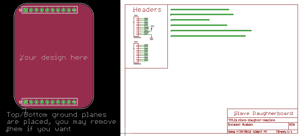
Developing a custom daughterboard is quite simple. We have created a blank daughterboard template with notes and documentation on the schematic to speed up the design process. Download the blank schematic and board files at the link below.
Place any components and connectors you desire and route the PCB. Make sure you do not change the location of the headers (the headers are locked parts, so you shouldn't be able to move them unless you unlock them).
We recommend OSH Park for fabrication of these small PCBs. You may order your PCB for $5 / square inch, and you will receive 3 copies of your design.
Custom header cable
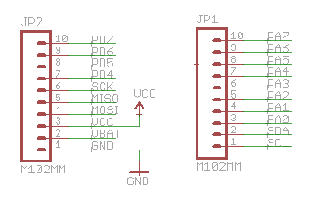
To make full use of the slave motherboard's I/O, you may design a simple cable for your custom sensors. Refer to the schematic below for pin functions:
- All PD* pins are capable of digital input and output - All PA* pins are capable of digital I/O and analog input (0v-3.3v) - SCK, MISO, and MOSI may be used for SPI or digital I/O - VCC is a regulated 3.3v supply - VBAT is a direct connection to battery voltage
Note: Pins labeled by PD* and PA* are referred to by this name in software. For instance, PA4 is referenced as pin 4 of PORTA in software.
To directly make use of these functions, you can directly solder wires to a male header and then insert the header into one of the slave daughterboard's female headers. Although this option is not as robust as a custom PCB, it allows for rapid prototyping of designs.
- Recommended male header: M22-2511005
Camera daughterboard auxilliary sensors
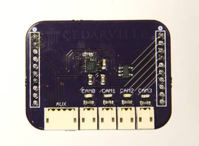
Each 2-pin port on the camera daughterboard can act as a digital output, digital input, or analog input (0v-3.3v). These connectors include a ground pin and a signal pin.
The camera daughterboard also includes a 5-pin connector for digital sensors. This connector includes I2C lines (SDA and SCL), a regulated 3.3v voltage supply, and a single digital input / output pin.
All of these connectors can be used for custom external sensors. At the minimum, you will likely need to use the 5-pin auxiliary connector to get 3.3v regulated power, which also provides digital I/O and I2C. If you need analog inputs, you will need to add additional 2-pin connectors for each required analog input.
Refer to the software configuration section below for configuring your inputs and outputs.
Writing slave firmware to support a new daughterboard
Adding a new daughterboard to the slave firmware is fairly simple. Follow the steps below to add your custom daughterboard or auxiliary sensors to the slave firmware.
1. Choose a blank module template
Several blank custom module templates have been created in the firmware for custom daughterboards:
- Custom 1 - DIP position 4
- Custom 2 - DIP position 5
- Custom 3 - DIP position 6
To use custom configurations, change the rotary DIP switch on the slave motherboard to position 4, 5, or 6.
Choose an unused custom module template and continue to the next step. It does not matter which you choose.
2. Configure Pins
If you are using simple digital or analog inputs or I2C sensors, startup configuration is already done for you. No additional code is required!
Additional configuration is only required if you are using the SPI module.
If you are using a SPI sensor, open modules.c and scroll to customX_setup() where “X” is the custom module you chose. Add a call to the setup_spi(); which will configure the SPI module to run at 172kHz. Feel free to modify the setup_spi() function if you desire to change the clock frequency (refer to the AVR manual for details).
3. Read the Sensor(s)
Each sensor is read by functions placed in the modules.c file at a configurable interval (which is set in config.h). To make custom daughterboard implementation easier, we have already created several empty functions for custom daughterboards. Open modules.c and scroll down to the function modules_custom1().
In this function you can read from any of your sensors. We have created some simple functions which perform simple digital and analog reading so you don't have to write much code.
Below is an example of a custom daughterboard. We started with the empty modules_custom1() function and added in some functions to read values from different pins.
void modules_custom1()
{
      // Read an analog value on PORTA pin 2 (PA2) and PORTA pin 5 (PA5)
      sensors_readAnalog(2);
      sensors_readAnalog(5);

      // Read a digital value from PORTA pin 6 (PA6)
      sensors_readDigitalPORTA(6);

      // Read a digital value from PORTD pin 6 (PD3)
      sensors_readDigitalPORTD(5);
}
If you want to read from digital sensors such as I2C or SPI, refer to the AVR manual and place all reading functionality inside this custom function.
4. Transmit Sensor Readings
Now that the slave is periodically reading your custom sensors, we need to make it transmit these readings to the master when the master requests the slave for data.
Open up masterComm.c and scroll down to the masterComm_modules() function.
Find the case statement for the module you are working on. In our example, we are using Custom 1 which corresponds to case 4.
Now you can get your sensor readings and prepare them for transmission to the master. If needed, you can perform any scaling / other math on your sensor readings before transmission.
You must assign a unique ID to each data type you transmit. For your sensors, choose any letter in the English alphabet. You can use uppercase or lowercase letters.
case 3:
  // Custom1

  // Send analog reading with some scaling and a linear offset
  masterComm_packetSend_signed('A', sensors_getAnalog(2) * 0.25 + 273.15);

  // Send analog reading without any preprocessing
  masterComm_packetSend_unsigned('B', sensors_getAnalog(5));

  // Send first digital reading
  masterComm_packetSend_unsigned('d',sensors_getDigital(6));

  // Send second digital reading
  masterComm_packetSend_unsigned('G',sensors_getDigital(5));

break;
The last change you need to make is updating definitions in config.h. DATATYPES_CUSTOM* constants define how many sensor readings we are going to transmit to the master.
Some onboard sensor readings are transmitted by default: battery voltage, board temperature, and heater status. For our example using Custom 1 we need to add 4 additional sensors (2 analog readings and 2 digital) to the 3 default sensors. This brings the total sensor count to 7, as shown below.
#define DATATYPES_CUSTOM1 7  // Modules already automatically send 3 values (temp, batt, and heater status.)
#define DATATYPES_CUSTOM2 3  //    Additional sensor readings should be added onto the 3
#define DATATYPES_CUSTOM3 3  //    For example a daughterboard with two sensors would be 3+2=5
Save, compile, and program your daughterboard. Set the DIP switch to the number corresponding with your chosen custom module (refer to the table in Step 1 above) and power on the module. You are now reading your custom sensors!


